Download as PDF, PPTX
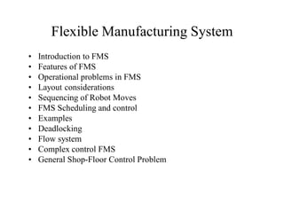
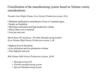
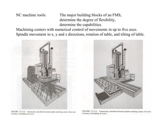
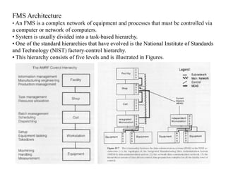
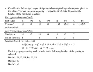
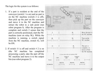
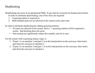
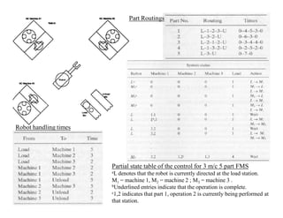
![A simple heuristic algorithm for circular and linear Single-Row machine
layouts:
Data required
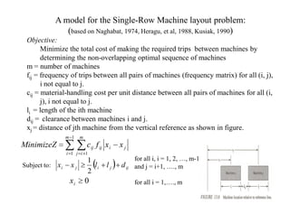
•m = number of machines
•fij = frequency of trips between all pairs of machines (frequency matrix) for all (i, j), i not equal
to j.
•cij = material-handling cost per unit distance between all pairs of machines for all (i, j), i not
equal to j.
Step 1: From the frequency and cost matrices, determine the adjusted flow matrix as follows:
F = [ f ij ] = [ f ij cij ]
Step 2: Determine f i ' j ' = max[ f ij , for .all .i.and . j ].
Obtain the partial solution by connecting i’ and j’. Set f i' j' = f j 'i ' = −∞
Step 3: Determine f p 'q ' = max[ f i 'k , f j 'l : k = 1,2,..., m; l = 1,2,...m].
Step 3.1: Connect q’ to p’ and add q’ to the partial solution.
Step 3.2: Delete row p’ and column p’ from [ f ij ]
Step 3.3: if p’ = i’, set i’ = q’; otherwise, set j’ = q’.
Step 4: Repeat step 3 until all the machines are included in the solution.](https://image.slidesharecdn.com/fms1-120913044519-phpapp02/85/Fms-1-28-320.jpg)
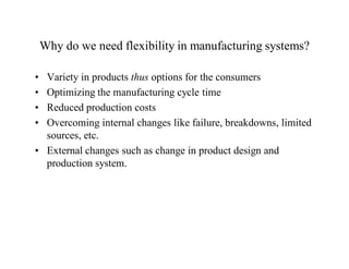
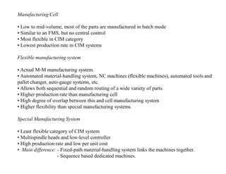
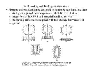
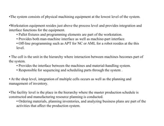
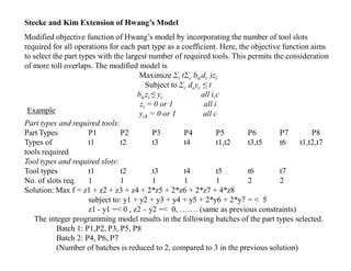
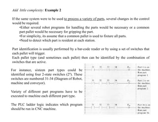
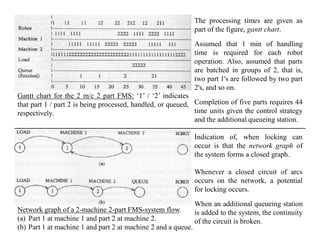
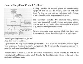
![Algorithm:Step 0: Calculate µ = 2ε + 4δ
Step 1: Calculate µ ≤ max {a, b}, then T2 is optimal. Calculate T2 and stop.
Otherwise go to step 2.
Step 2: If µ > max {a, b} and 2δ ≤ a + b, then T2 is optimal. Calculate T2 and stop.
Otherwise go to step 3.
Step 3: If µ > max {a, b} and 2δ > a + b, then T1 is optimal. Calculate T1 and stop.
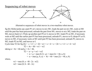
Example: Determine the optimal cycle time and corresponding robot sequences in a two-
machine robotic cell with the following data:
Processing time of Machine M1 =11.00 min
Processing time of Machine M2 =09.00 min
Robot gripper pickup = 0.16 min
Robot gripper release time = 0.16 min
Robot move time between the two machines = 0.24 min
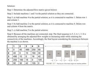
Solution:
Step 0: µ = 2ε + 4δ
µ = 2(0.16) + 4(0.24) = 1.28 min
Step 1: µ ≤ max {a, b}
1.28 ≤ max {11, 9}, i.e.1.28 < 11. Therefore, T2 is optimal.
T2 = α + max {µ, a, b}
T2 = [4ε + 4δ] + max {1.28, 11, 9} = [4(0.16) + 4(0.24)] + 11
T2 = 1.6 + 11 = 12.6 min
The optimal cycle time is 12.6 min and the optimal robot is given by fig (b) as shown in the
previous slide.](https://image.slidesharecdn.com/fms1-120913044519-phpapp02/85/Fms-1-33-320.jpg)

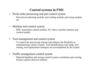
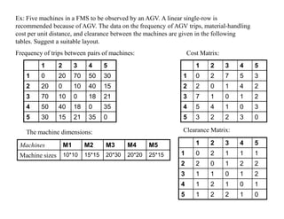
The adjusted flow matrix is obtained as: F = [[0, 40, 490, 250, 180], [40, 0, 70, 200, 120], [490, 70, 0, 280, 210], [250, 200, 280, 0, 150], [180, 120, 210, 150, 0]] The heuristic algorithm provides the following sequence: 3 - 1 - 4 - 2 - 5 Hence, the recommended linear single row layout is: 3 1 4 2 5 This minimizes the total material handling cost by placing machines with highest flow between them closest. The clearance between machines must also be ensured as per the data provided.


![Lecture 25 flexible manufacturing systems [compatibility mode]](https://cdn.slidesharecdn.com/ss_thumbnails/lecture25flexiblemanufacturingsystemscompatibilitymode-140111213832-phpapp01-thumbnail.jpg?width=640&height=640&fit=bounds)


