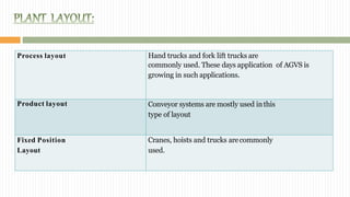
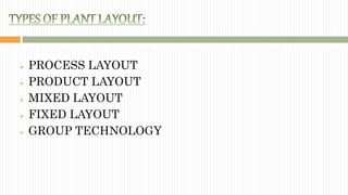
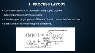
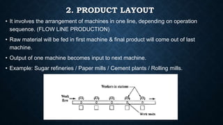
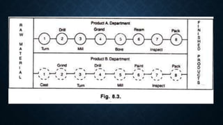
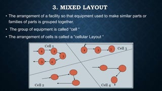
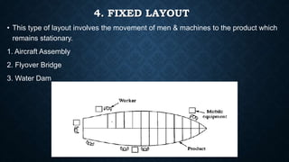
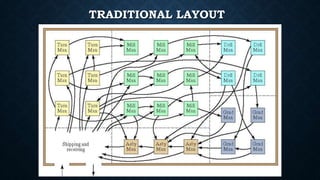
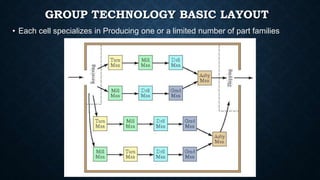
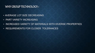
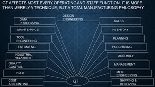
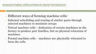
- By Paarth Gupta
 Plant Layout is the physical arrangement of equipment and
facilities within a plant.
 It is the way the equipment is physically arranged in the
factory.
 Plant layout is the organization of physical facilities like
machinery, equipment & the allocation of space for the various
activities of the plant & personnel working in the plant.
 A method of organizing the elements of a production process,
in which similar processes and functions are grouped together.
Process layout Hand trucks and fork lift trucks are
commonly used. These days application of AGVS is
growing in such applications.
Product layout Conveyor systems are mostly used inthis
type of layout
Fixed Position
Layout
Cranes, hoists and trucks arecommonly
used.
 A new product
 A new plant
 A new product design
 Addition/Deletion of new machine
 MATERIALS (types of raw materials and availability)
 PRODUCT (types of product and its position)
 WORKER (type, position and requirements)
 MACHINERY (product, volume and process)
 INDUSTRY (type of industry)
 PLANT ENVIRONMENT
 PROCESS LAYOUT
 PRODUCT LAYOUT
 MIXED LAYOUT
 FIXED LAYOUT
 GROUP TECHNOLOGY
1. PROCESS LAYOUT
• Common operations or processes are grouped together.
• General purpose machines are used.
• It involves grouping together of like machines in one section/ department.
• Best suited for intermittent type of operations.
While grouping machines certain principles needed to be kept
in mind :-
• The distance between departments should be as short as possible.
• Machines should be grouped in accordance with the principle of sequence of
operation within the department.
• Convenience for inspection.
• Convenience for supervision.
Advantages:
• Easy to handle machine breakdown by transfer of to another machine.
• Product design is flexible.
• Investment on equipment will be comparatively low.
• Full utilization of equipment.
Disadvantages:
• Requires more floor space.
• Difficulty in movement of material.
• Production control is difficult i.e. mass production is not involved.
• High production time as material has to travel from place to place.
2. PRODUCT LAYOUT
• It involves the arrangement of machines in one line, depending on operation
sequence. (FLOW LINE PRODUCTION)
• Raw material will be fed in first machine & final product will come out of last
machine.
• Output of one machine becomes input to next machine.
• Example: Sugar refineries / Paper mills / Cement plants / Rolling mills.
Advantages:
• Smooth & regular flow of finished goods.
• Shorter processing time due to less travel, storage & inspection frequency.
• Reduced material handling.
• Low cost labors & lesser training requirement.
• Use of special purpose machines (SPM) ,automatic or semi-automatic.
• Easy production control.
Disadvantages:
• Heavy capital investment.
• Non flexible layout.
• Risk of total production line shutdown.
PRODUCT VS PROCESS LAYOUT
3. MIXED LAYOUT
• The arrangement of a facility so that equipment used to make similar parts or
families of parts is grouped together.
• The group of equipment is called “cell “
• The arrangement of cells is called a “cellular Layout “
4. FIXED LAYOUT
• This type of layout involves the movement of men & machines to the product which
remains stationary.
1. Aircraft Assembly
2. Flyover Bridge
3. Water Dam
Advantages:
• The investment on layout is very small.
• The high cost & difficulty in transporting a bulky product are avoided.
Disadvantages:
• High cost of operation.
• Very high duration of project.
• Rework will be very costly.
4. GROUP TECHNOLOGY
A manufacturing philosophy in which similar parts are identified
and grouped together to take advantage of their similarities in
design and production.
Group technology becomes especially attractive because of the ever-
greater variety of products available to consumers, which are often
produced in batches.
The traditional product flow in batch manufacturing, the process-
oriented layout, creates large amount of transportation and WIP. A
more efficient product flow line to take advantage of group
technology is the product-oriented layout or to form a manufacturing
cell.
TRADITIONAL LAYOUT
GROUP TECHNOLOGY BASIC LAYOUT
• Each cell specializes in Producing one or a limited number of part families
WHY GROUP TECHNOLOGY:-
• AVERAGE LOT SIZE DECREASING
• PART VARIETY INCREASING
• INCREASED VARIETY OF MATERIALS WITH DIVERSE PROPERTIES
• REQUIREMENTS FOR CLOSER TOLERANCES
GT AFFECTS MOST EVERY OPERATING AND STAFF FUNCTION. IT IS MORE
THAN MERELY A TECHNIQUE, BUT A TOTAL MANUFACTURING PHILOSOPHY.
GT
DESIGN
ENGINEERINGDATA
PROCESSING
MAINTENANCE
TOOL
ENGINEERING
ESTIMATING
INDUSTRIAL
RELATIONS
QUALITY
CONTROL
R & D
COST
ACCOUNTING
SALES
INVENTORY
PLANNING
PURCHASING
ASSEMBLY
MANAGEMENT
MFG.
ENGINEERING
SHIPPING &
RECEIVING
 Different ways of forming machine cells:
 Informal scheduling and routing of similar parts through
selected machines to minimize setups
 Virtual machine cells – dedication of certain machines in the
factory to produce part families, but no physical relocation of
machines
 Formal machine cells – machines are physically relocated to
form the cells.
 Automated process planning
 Modular fixtures
 Parametric programming in NC
 Standardization of tooling, fixtures, and setups is encouraged.
 Material handling is reduced. Parts are moved within a
machine cell rather than the Entire factory.
 Process planning and production scheduling are simplified.
 Higher quality work
 In group technology, parts are identified and grouped into
families by classification and coding (C/C) systems. This
process is a critical and complex first step and is done
according to the part’s design attributes and manufacturing
attributes.
 Part design attributes
 Part manufacturing attributes
Part manufacturing attributes
 Major dimensions
 Basic external shape
 Basic internal shape
 Length/diameter ratio
 Material type
 Part function
 Tolerances
 Surface finish
 Major process
 Operation sequence
 Batch size
 Annual production
 Machine tools
 Cutting tools
 Material type
Part design attributes
The Opitz system was developed in the 1960s in Germany by H.
Opitz (1905-1977), and was the first comprehensive coding system
presented. Basic code = nine (9) digits
 Digits 1 through 5 = form code – primary shape and design
attributes (hierarchical structure)
 Digits 6 through 9 = supplementary code – attributes that are
useful in manufacturing (e.g., dimensions, starting material)
 Digits 10 through 13 = secondary code – production operation
type and sequence
 The basic layouts of group technology are:
1. Progressive or Line Type
2. Loop Type
3. Ladder Type
4. Open field type
NOW LET US DISCUSS ABOUT THE LATEST TRENDS
IN FMS
A flexible manufacturing system (FMS) is a set of numerically
controlled machine tools and supporting workstations connected by an
automated material handling system and all aspects of the system
controlled by a central computer.
 FMS is distinguished from an automated production line by its ability
to process more than one product style simultaneously.
 At any moment, each machine in the system may be processing a
different part type.
 FMS can let us make changes in production schedule in order to
meet the demands on different products.
 Minimizing the process cycle time: The process must be designed to
minimize machining and handling.
 Maximizing the utilization of each machine: This can be done by
balancing the work load in the system and real time scheduling.
 Backup capabilities: The system should be able to run even when
failures occur.
 Use of identification marking techniques: Bar codes and RFID tags
are now popular for identifying products as well as components. This
permits automatic tracking of workpieces and tools.
 Use of automated storage systems to keep work ready for
machines to process: The raw work parts must be replenished as
and when needed to avoid starving the work centres.
 Provision of adequate sensors for the detection of errors or
problems: This includes the detection of the presence and
absence of parts, jamming, tool wear, machine failures, and so on..
plant layout

plant layout

  • 1.
  • 3.
     Plant Layoutis the physical arrangement of equipment and facilities within a plant.  It is the way the equipment is physically arranged in the factory.  Plant layout is the organization of physical facilities like machinery, equipment & the allocation of space for the various activities of the plant & personnel working in the plant.  A method of organizing the elements of a production process, in which similar processes and functions are grouped together.
  • 5.
    Process layout Handtrucks and fork lift trucks are commonly used. These days application of AGVS is growing in such applications. Product layout Conveyor systems are mostly used inthis type of layout Fixed Position Layout Cranes, hoists and trucks arecommonly used.
  • 6.
     A newproduct  A new plant  A new product design  Addition/Deletion of new machine
  • 7.
     MATERIALS (typesof raw materials and availability)  PRODUCT (types of product and its position)  WORKER (type, position and requirements)  MACHINERY (product, volume and process)  INDUSTRY (type of industry)  PLANT ENVIRONMENT
  • 8.
     PROCESS LAYOUT PRODUCT LAYOUT  MIXED LAYOUT  FIXED LAYOUT  GROUP TECHNOLOGY
  • 9.
    1. PROCESS LAYOUT •Common operations or processes are grouped together. • General purpose machines are used. • It involves grouping together of like machines in one section/ department. • Best suited for intermittent type of operations.
  • 10.
    While grouping machinescertain principles needed to be kept in mind :- • The distance between departments should be as short as possible. • Machines should be grouped in accordance with the principle of sequence of operation within the department. • Convenience for inspection. • Convenience for supervision.
  • 11.
    Advantages: • Easy tohandle machine breakdown by transfer of to another machine. • Product design is flexible. • Investment on equipment will be comparatively low. • Full utilization of equipment. Disadvantages: • Requires more floor space. • Difficulty in movement of material. • Production control is difficult i.e. mass production is not involved. • High production time as material has to travel from place to place.
  • 12.
    2. PRODUCT LAYOUT •It involves the arrangement of machines in one line, depending on operation sequence. (FLOW LINE PRODUCTION) • Raw material will be fed in first machine & final product will come out of last machine. • Output of one machine becomes input to next machine. • Example: Sugar refineries / Paper mills / Cement plants / Rolling mills.
  • 14.
    Advantages: • Smooth &regular flow of finished goods. • Shorter processing time due to less travel, storage & inspection frequency. • Reduced material handling. • Low cost labors & lesser training requirement. • Use of special purpose machines (SPM) ,automatic or semi-automatic. • Easy production control. Disadvantages: • Heavy capital investment. • Non flexible layout. • Risk of total production line shutdown.
  • 15.
  • 16.
    3. MIXED LAYOUT •The arrangement of a facility so that equipment used to make similar parts or families of parts is grouped together. • The group of equipment is called “cell “ • The arrangement of cells is called a “cellular Layout “
  • 17.
    4. FIXED LAYOUT •This type of layout involves the movement of men & machines to the product which remains stationary. 1. Aircraft Assembly 2. Flyover Bridge 3. Water Dam
  • 18.
    Advantages: • The investmenton layout is very small. • The high cost & difficulty in transporting a bulky product are avoided. Disadvantages: • High cost of operation. • Very high duration of project. • Rework will be very costly.
  • 19.
    4. GROUP TECHNOLOGY Amanufacturing philosophy in which similar parts are identified and grouped together to take advantage of their similarities in design and production. Group technology becomes especially attractive because of the ever- greater variety of products available to consumers, which are often produced in batches. The traditional product flow in batch manufacturing, the process- oriented layout, creates large amount of transportation and WIP. A more efficient product flow line to take advantage of group technology is the product-oriented layout or to form a manufacturing cell.
  • 20.
  • 21.
    GROUP TECHNOLOGY BASICLAYOUT • Each cell specializes in Producing one or a limited number of part families
  • 22.
    WHY GROUP TECHNOLOGY:- •AVERAGE LOT SIZE DECREASING • PART VARIETY INCREASING • INCREASED VARIETY OF MATERIALS WITH DIVERSE PROPERTIES • REQUIREMENTS FOR CLOSER TOLERANCES
  • 23.
    GT AFFECTS MOSTEVERY OPERATING AND STAFF FUNCTION. IT IS MORE THAN MERELY A TECHNIQUE, BUT A TOTAL MANUFACTURING PHILOSOPHY. GT DESIGN ENGINEERINGDATA PROCESSING MAINTENANCE TOOL ENGINEERING ESTIMATING INDUSTRIAL RELATIONS QUALITY CONTROL R & D COST ACCOUNTING SALES INVENTORY PLANNING PURCHASING ASSEMBLY MANAGEMENT MFG. ENGINEERING SHIPPING & RECEIVING
  • 24.
     Different waysof forming machine cells:  Informal scheduling and routing of similar parts through selected machines to minimize setups  Virtual machine cells – dedication of certain machines in the factory to produce part families, but no physical relocation of machines  Formal machine cells – machines are physically relocated to form the cells.
  • 25.
     Automated processplanning  Modular fixtures  Parametric programming in NC  Standardization of tooling, fixtures, and setups is encouraged.  Material handling is reduced. Parts are moved within a machine cell rather than the Entire factory.  Process planning and production scheduling are simplified.  Higher quality work
  • 26.
     In grouptechnology, parts are identified and grouped into families by classification and coding (C/C) systems. This process is a critical and complex first step and is done according to the part’s design attributes and manufacturing attributes.  Part design attributes  Part manufacturing attributes
  • 27.
    Part manufacturing attributes Major dimensions  Basic external shape  Basic internal shape  Length/diameter ratio  Material type  Part function  Tolerances  Surface finish  Major process  Operation sequence  Batch size  Annual production  Machine tools  Cutting tools  Material type Part design attributes
  • 28.
    The Opitz systemwas developed in the 1960s in Germany by H. Opitz (1905-1977), and was the first comprehensive coding system presented. Basic code = nine (9) digits  Digits 1 through 5 = form code – primary shape and design attributes (hierarchical structure)  Digits 6 through 9 = supplementary code – attributes that are useful in manufacturing (e.g., dimensions, starting material)  Digits 10 through 13 = secondary code – production operation type and sequence
  • 30.
     The basiclayouts of group technology are: 1. Progressive or Line Type 2. Loop Type 3. Ladder Type 4. Open field type
  • 31.
    NOW LET USDISCUSS ABOUT THE LATEST TRENDS IN FMS
  • 32.
    A flexible manufacturingsystem (FMS) is a set of numerically controlled machine tools and supporting workstations connected by an automated material handling system and all aspects of the system controlled by a central computer.  FMS is distinguished from an automated production line by its ability to process more than one product style simultaneously.  At any moment, each machine in the system may be processing a different part type.  FMS can let us make changes in production schedule in order to meet the demands on different products.
  • 33.
     Minimizing theprocess cycle time: The process must be designed to minimize machining and handling.  Maximizing the utilization of each machine: This can be done by balancing the work load in the system and real time scheduling.  Backup capabilities: The system should be able to run even when failures occur.  Use of identification marking techniques: Bar codes and RFID tags are now popular for identifying products as well as components. This permits automatic tracking of workpieces and tools.
  • 34.
     Use ofautomated storage systems to keep work ready for machines to process: The raw work parts must be replenished as and when needed to avoid starving the work centres.  Provision of adequate sensors for the detection of errors or problems: This includes the detection of the presence and absence of parts, jamming, tool wear, machine failures, and so on..