Downloaded 200 times


![Latch Inference - Incomplete case Statements
// Creating a latch
module latch_infer_case(select, data, y);
input select;
output y;
reg y;
always @(select or data)
case (select)
2'b00: y = data[select];
2'b01: y = data[select];
2'b10: y = data[select];
// default: y = 2'b11;
endcase
No Default Statement – Infers a latch
// Correct code
module latch_infer_case(select, data, y);
input select;
output y;
reg y;
always @(select or data)
case (select)
2'b00: y = data[select];
2'b01: y = data[select];
2'b10: y = data[select];
default: y = 2'b11;
endcase](https://image.slidesharecdn.com/codingstyleforgoodsynthesis-130911005351-phpapp02/75/Coding-style-for-good-synthesis-17-2048.jpg)


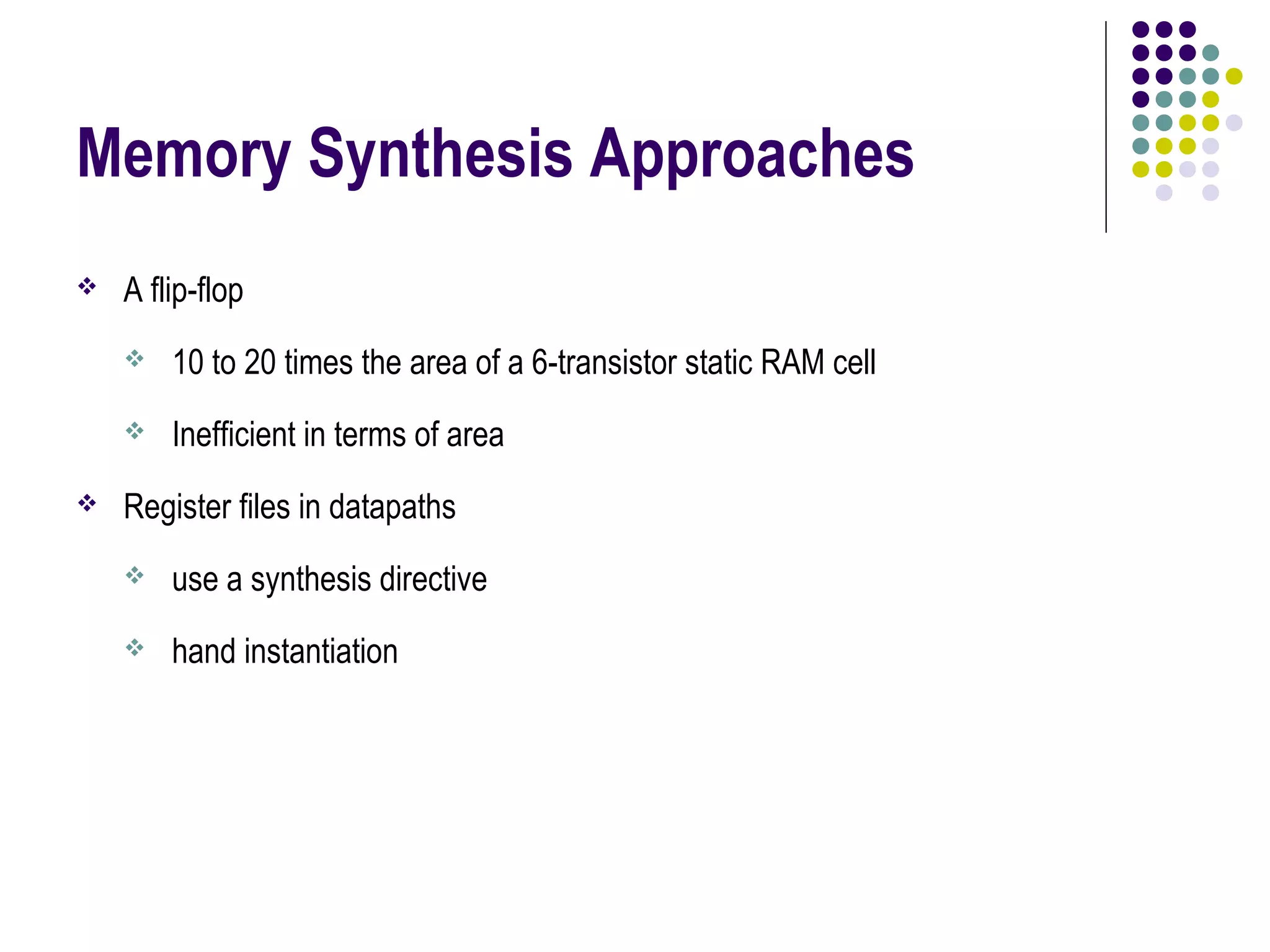


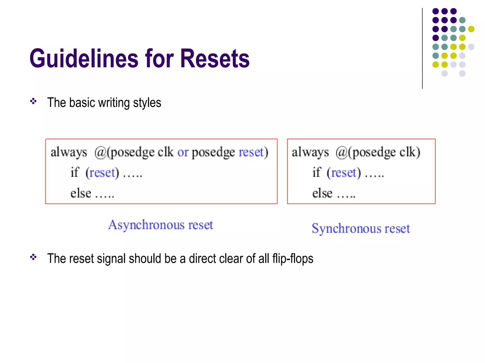
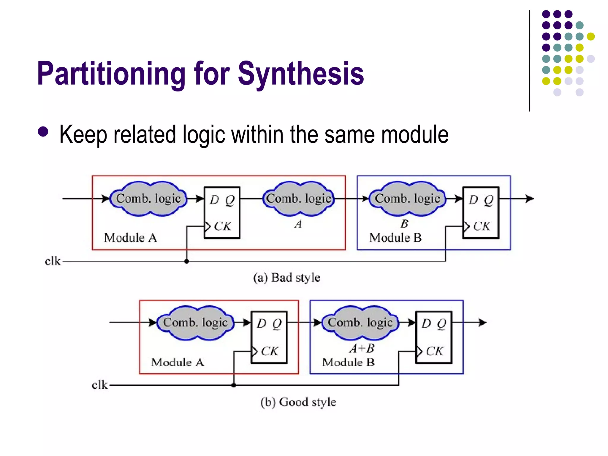


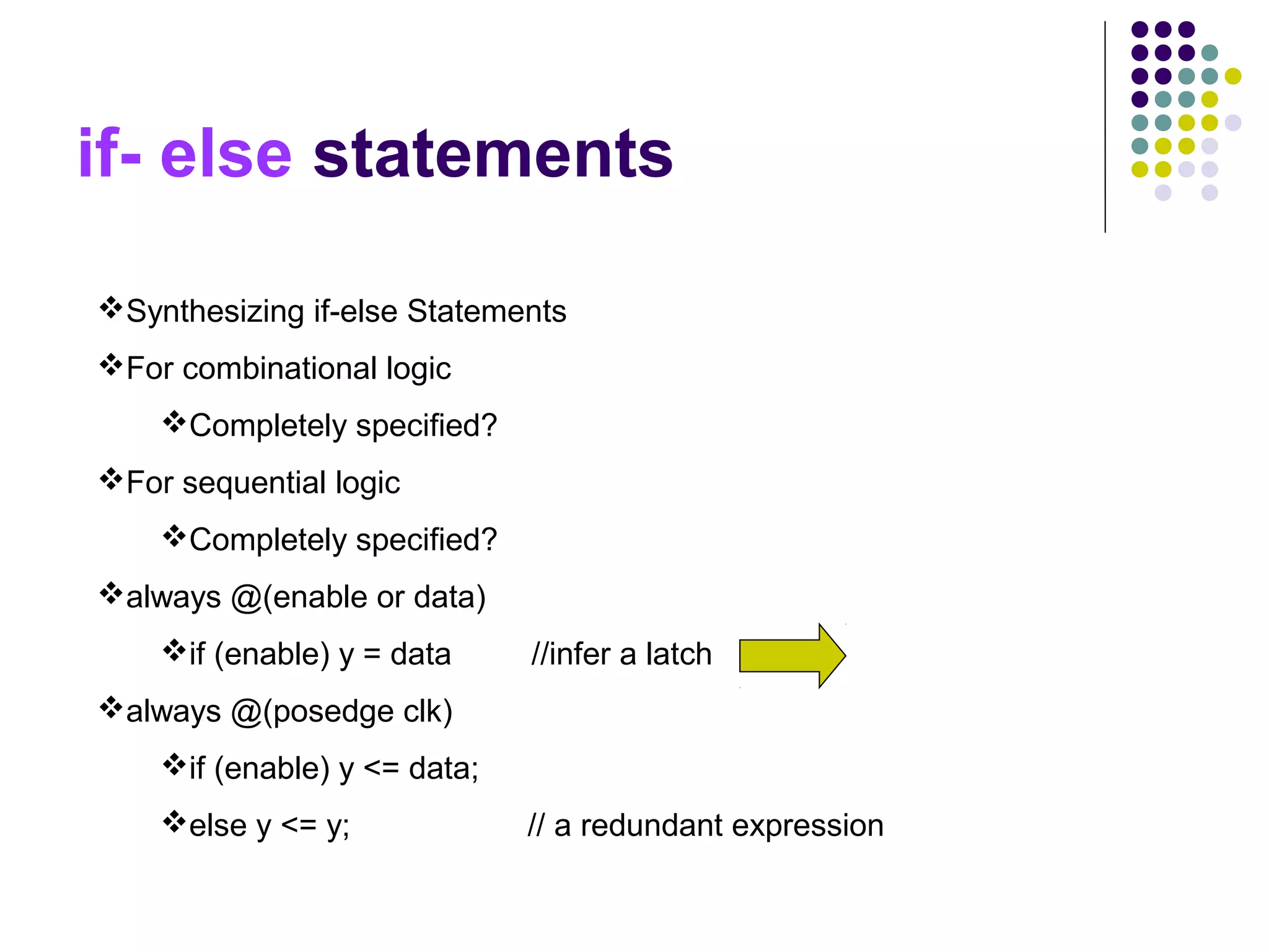
This document discusses coding style guidelines for logic synthesis. It begins with basic concepts of logic synthesis such as converting a high-level design to a gate-level representation using a standard cell library. It then discusses synthesizable Verilog constructs and coding techniques to improve synthesis like using non-blocking assignments in sequential logic blocks. The document also provides guidelines for coding constructs like if-else statements, case statements, always blocks and loops to make the design easily synthesizable. Memory synthesis approaches and techniques for designing clocks and resets are also covered.


![Lecture 25 flexible manufacturing systems [compatibility mode]](https://cdn.slidesharecdn.com/ss_thumbnails/lecture25flexiblemanufacturingsystemscompatibilitymode-140111213832-phpapp01-thumbnail.jpg?width=640&height=640&fit=bounds)