Downloaded 512 times
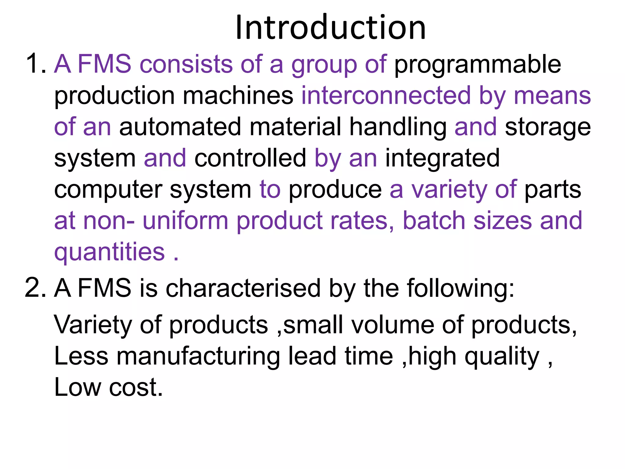
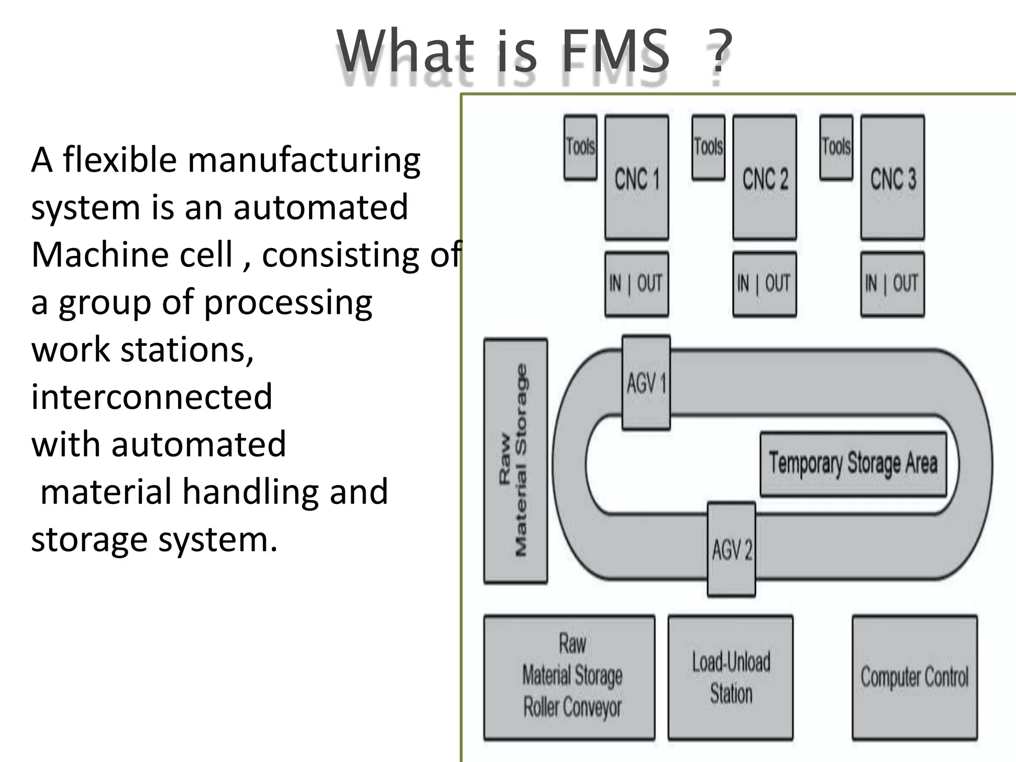
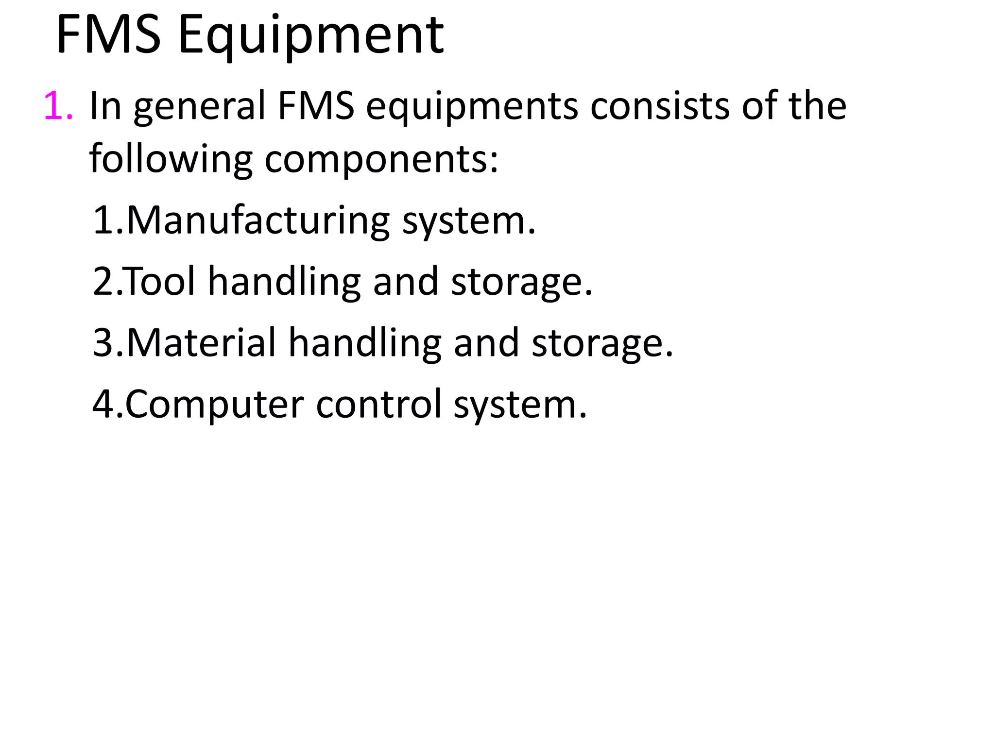
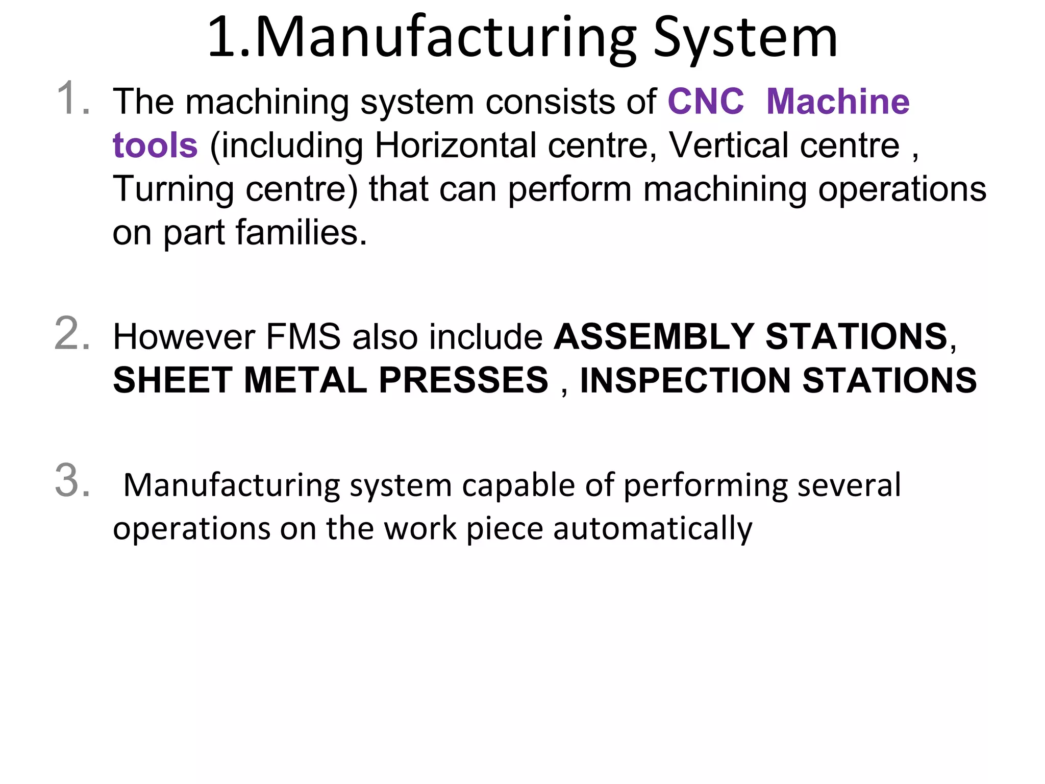


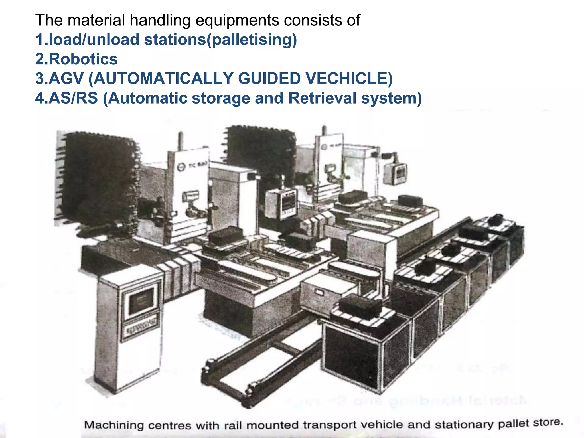


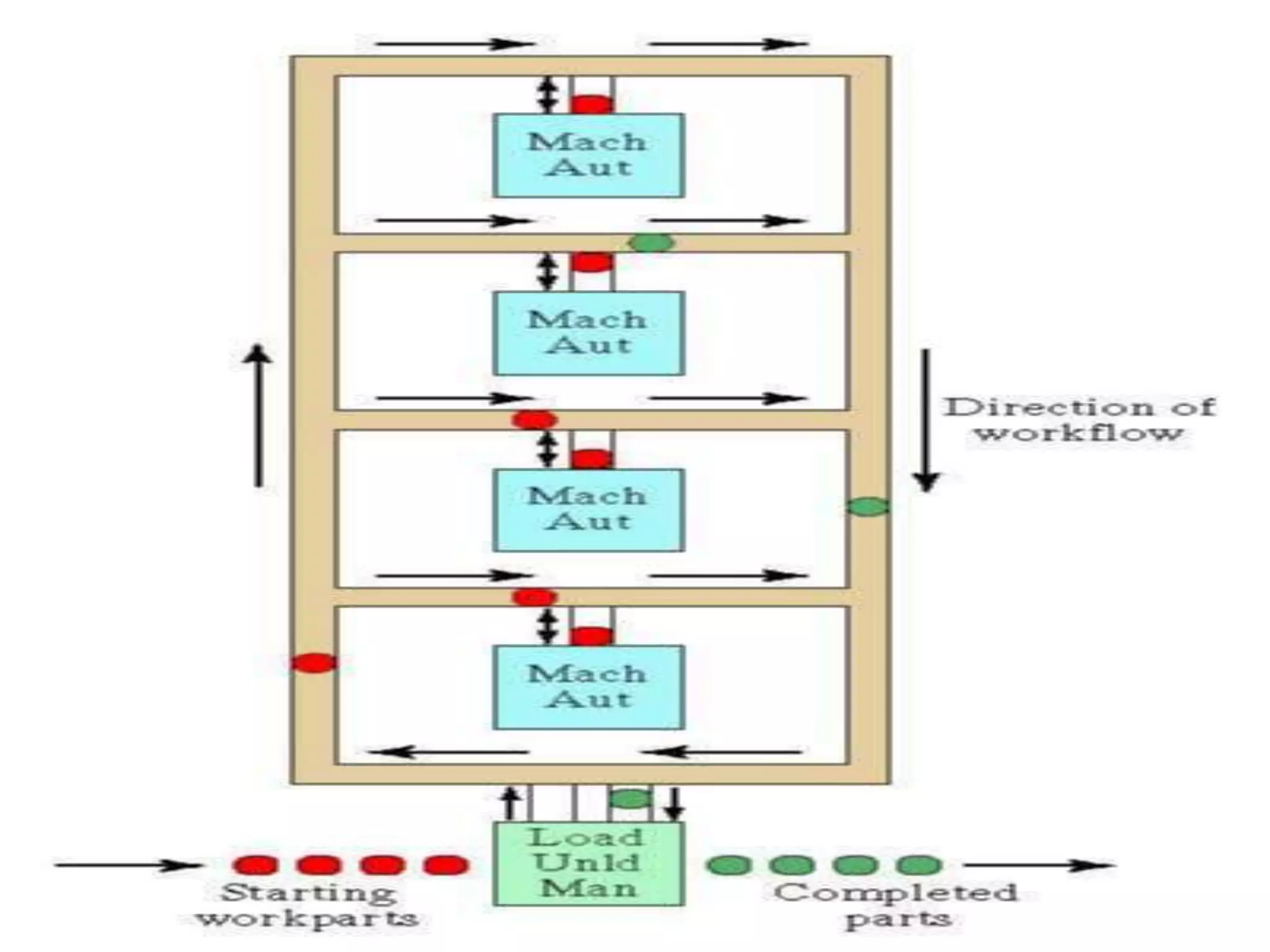


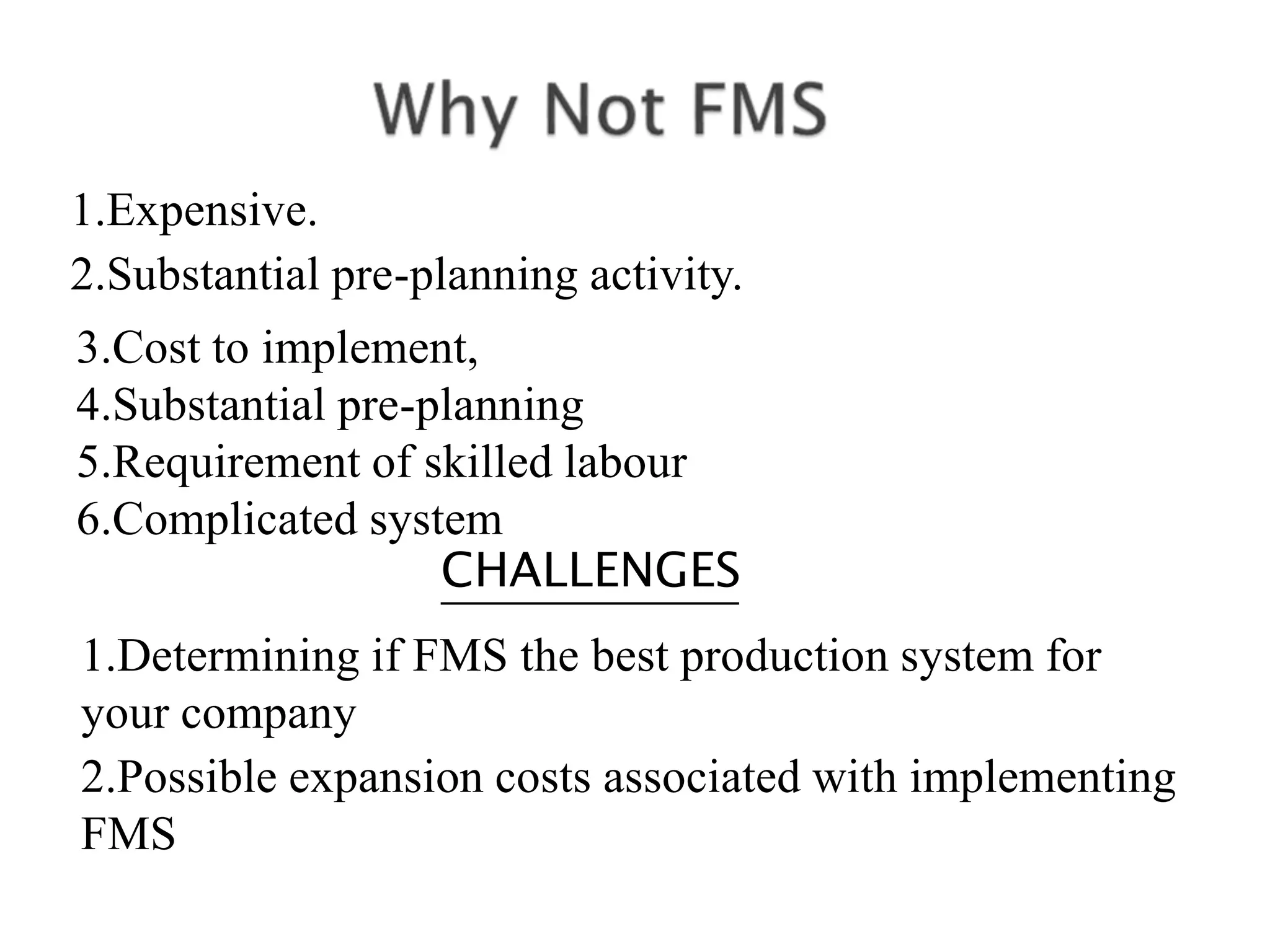


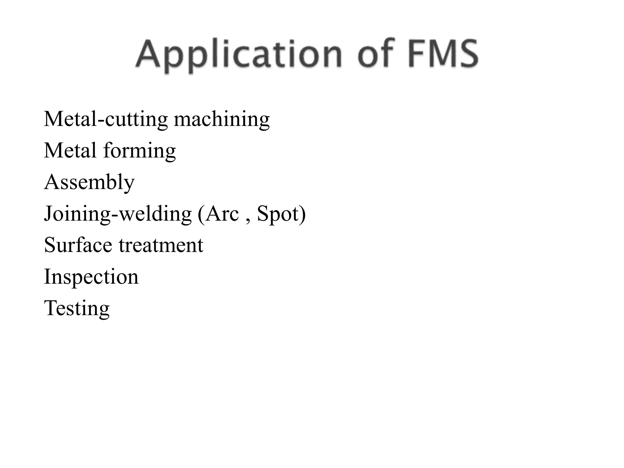


A Flexible Manufacturing System (FMS) consists of programmable production machines interconnected by automated material handling systems, capable of producing various parts with high quality and low costs. Key components include manufacturing systems, tool handling, material handling, storage, and a computer control system, enabling real-time operation and control. FMS offers benefits like flexibility, reduced lead times, and improved productivity, while also facing challenges such as high implementation costs and the need for skilled labor.


![Lecture 25 flexible manufacturing systems [compatibility mode]](https://cdn.slidesharecdn.com/ss_thumbnails/lecture25flexiblemanufacturingsystemscompatibilitymode-140111213832-phpapp01-thumbnail.jpg?width=640&height=640&fit=bounds)