Downloaded 382 times

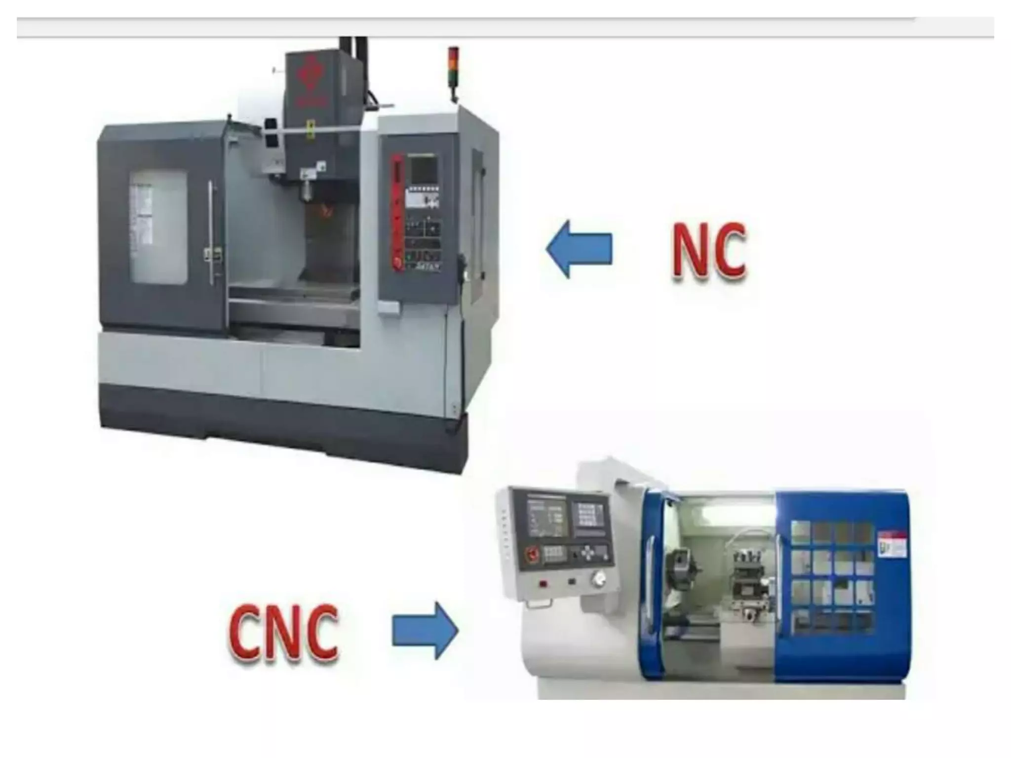
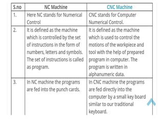
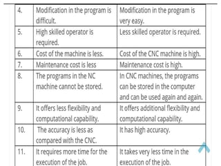
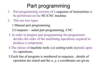
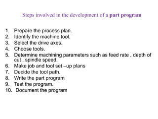
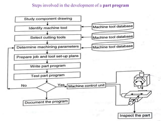
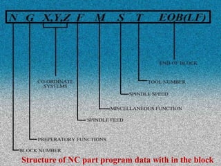
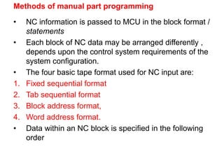
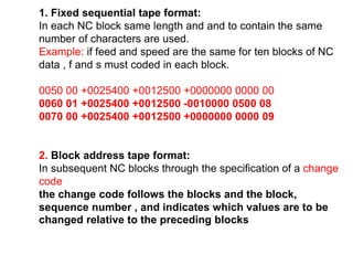
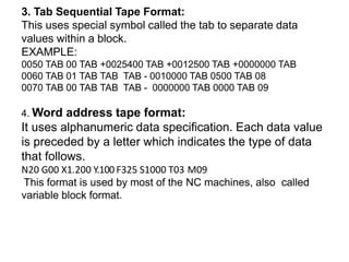
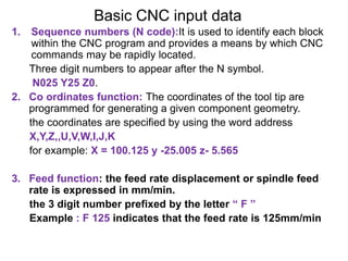
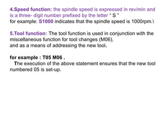
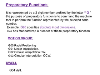
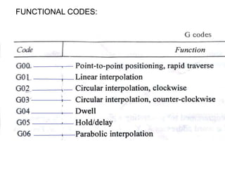
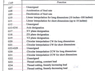
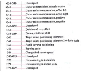
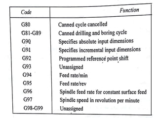
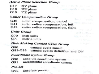
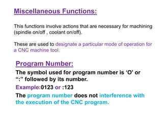
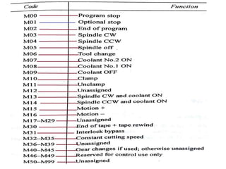
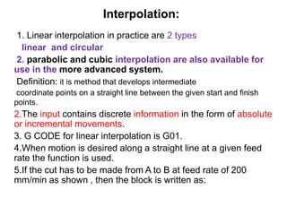

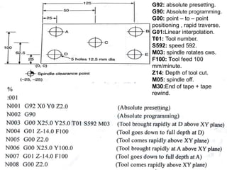
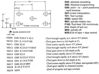
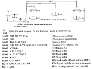

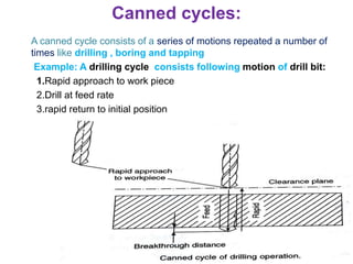

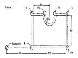


Part programming involves creating a sequence of instructions for NC/CNC machines, which can be either manual or computer-aided. The process includes preparing a process plan, selecting tools, and determining machining parameters before writing and testing the part program. Different formats, such as fixed sequential and word address tape formats, are used to structure NC data, and various functions like tool changes and motion types are specified through codes.