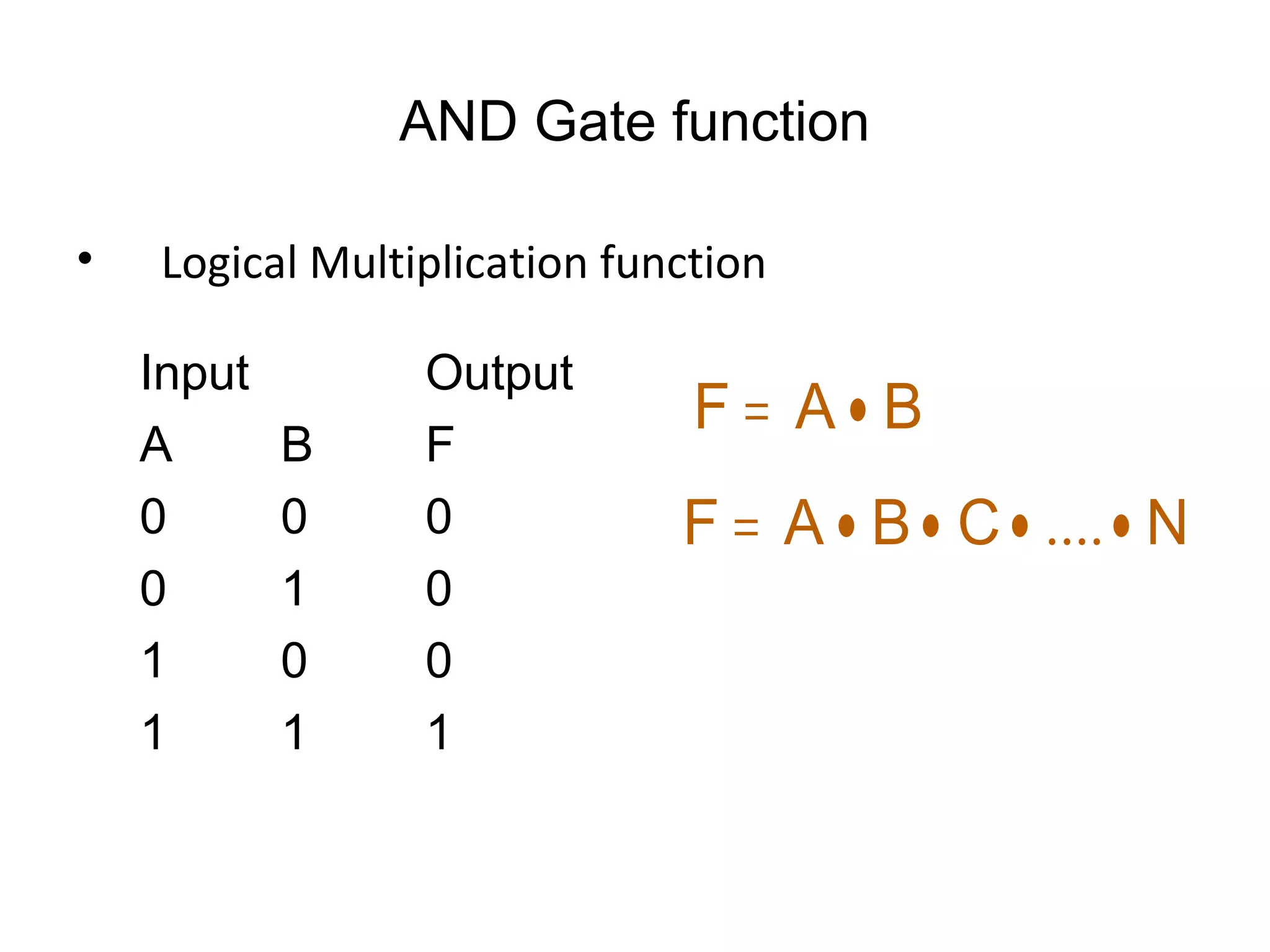
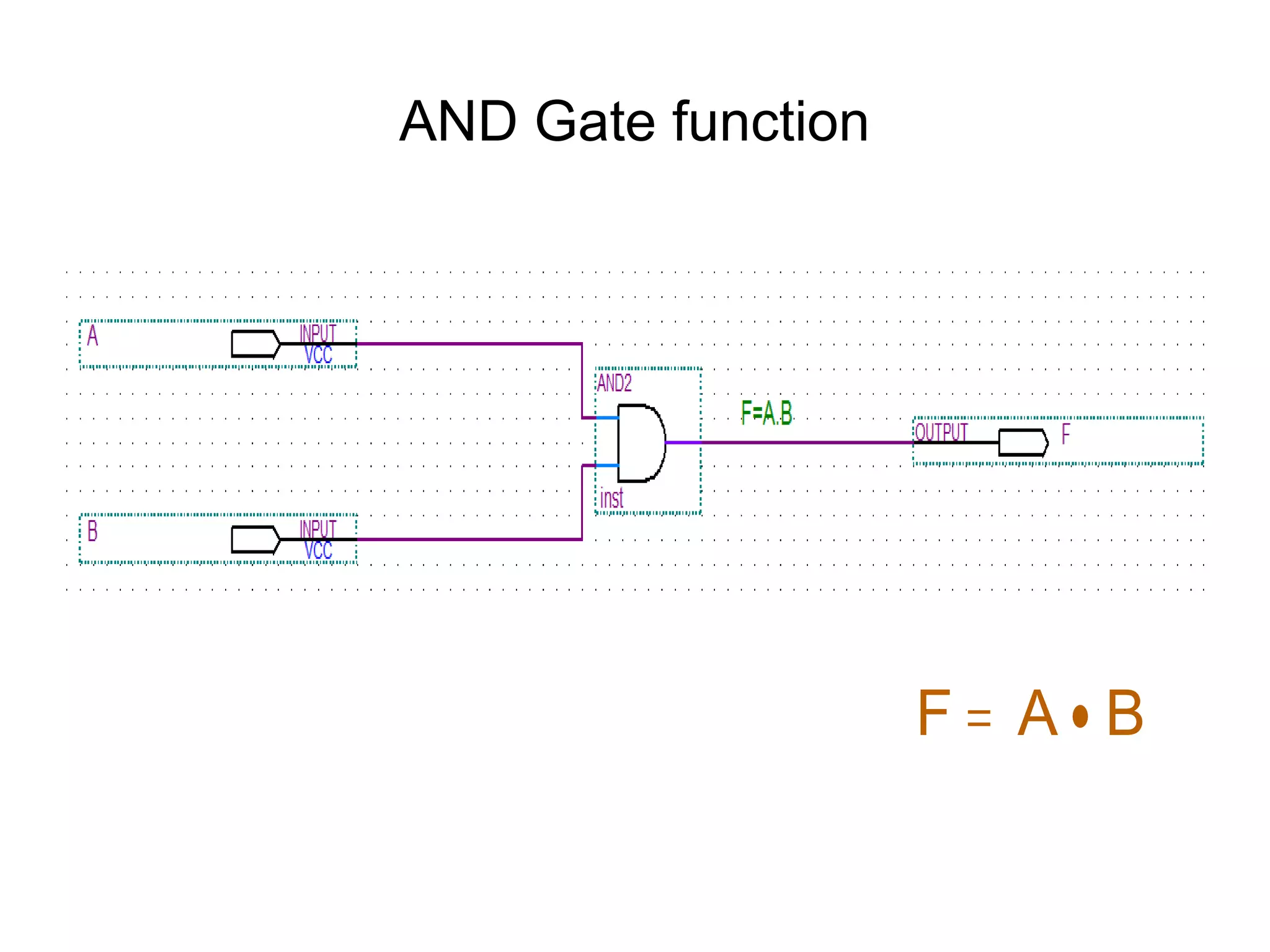
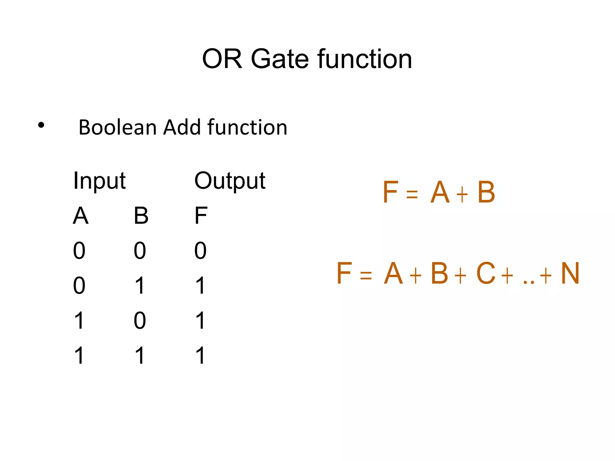
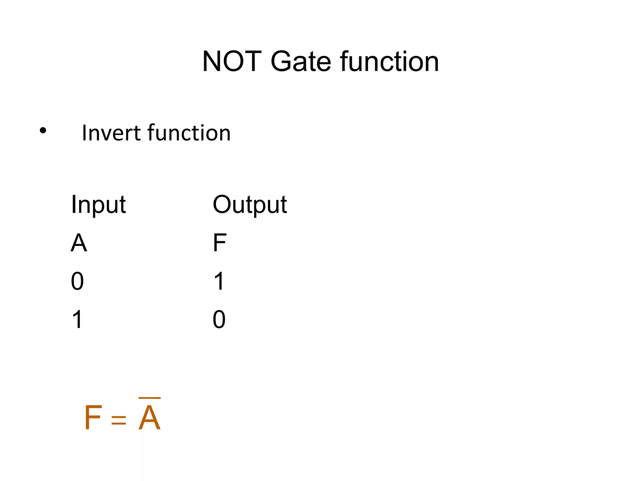
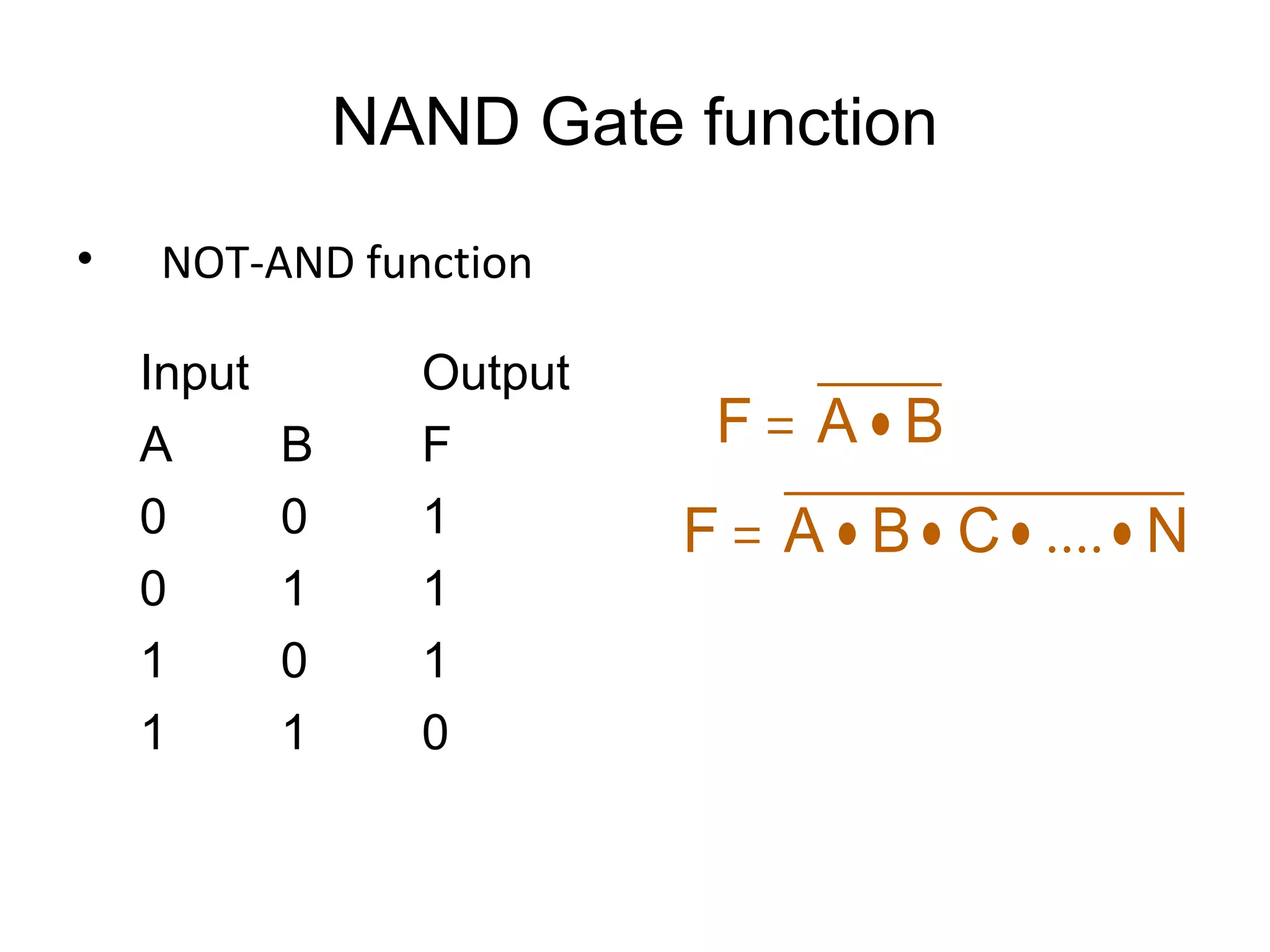
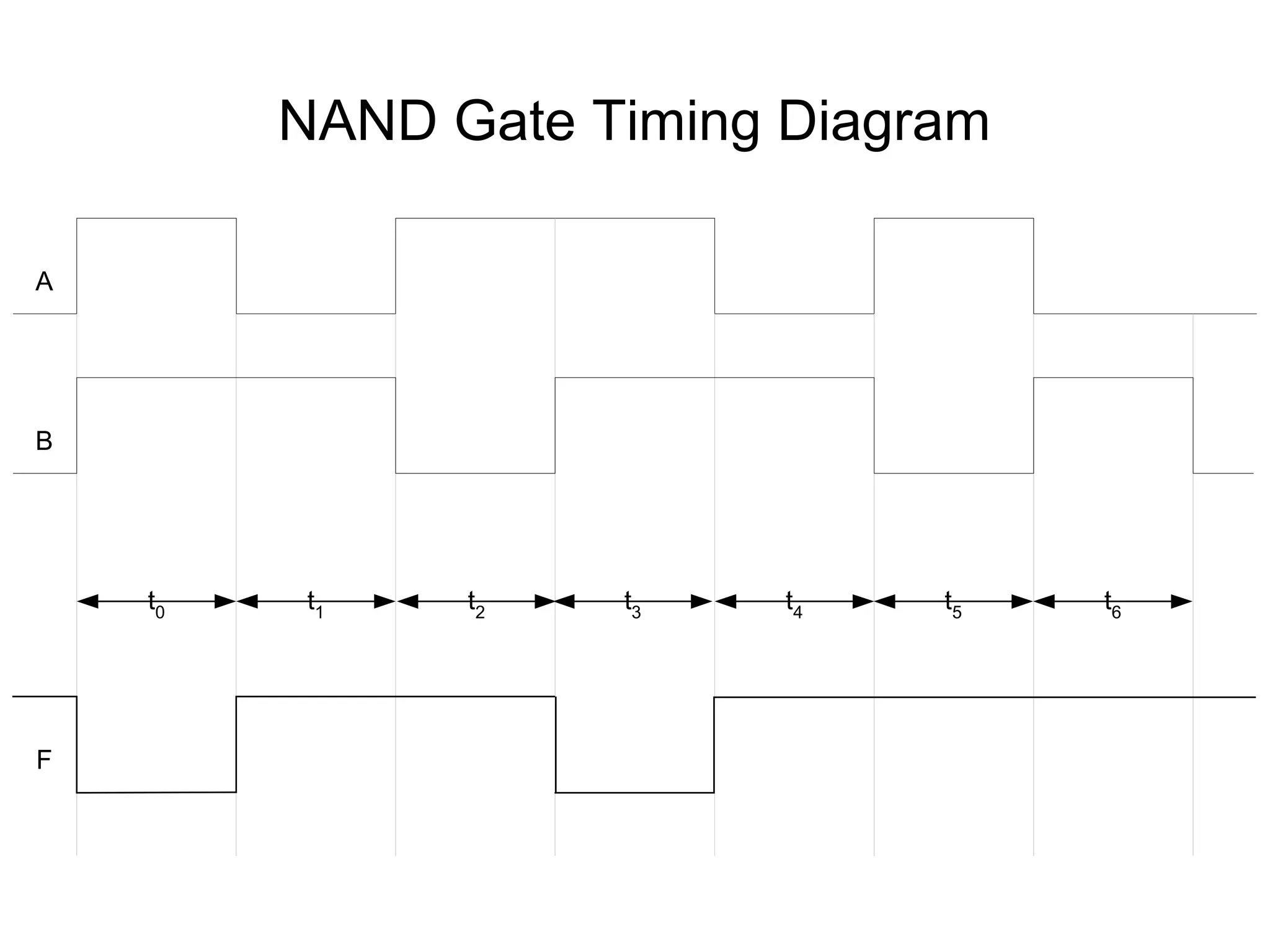
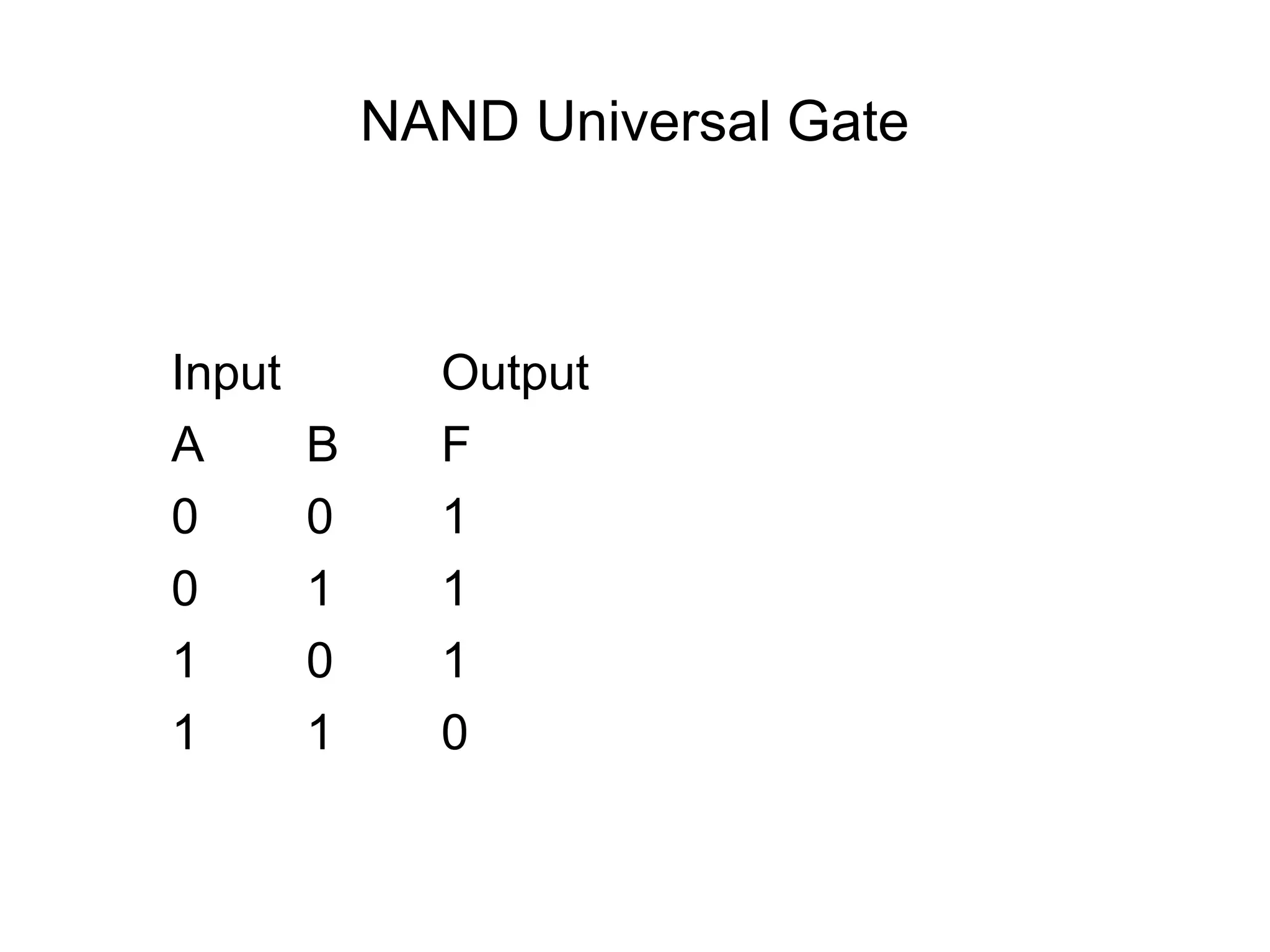
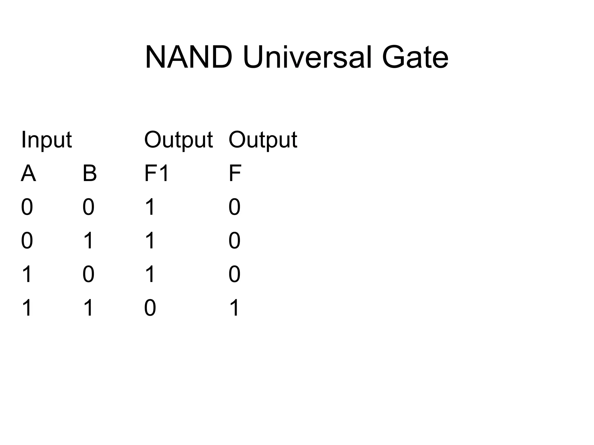
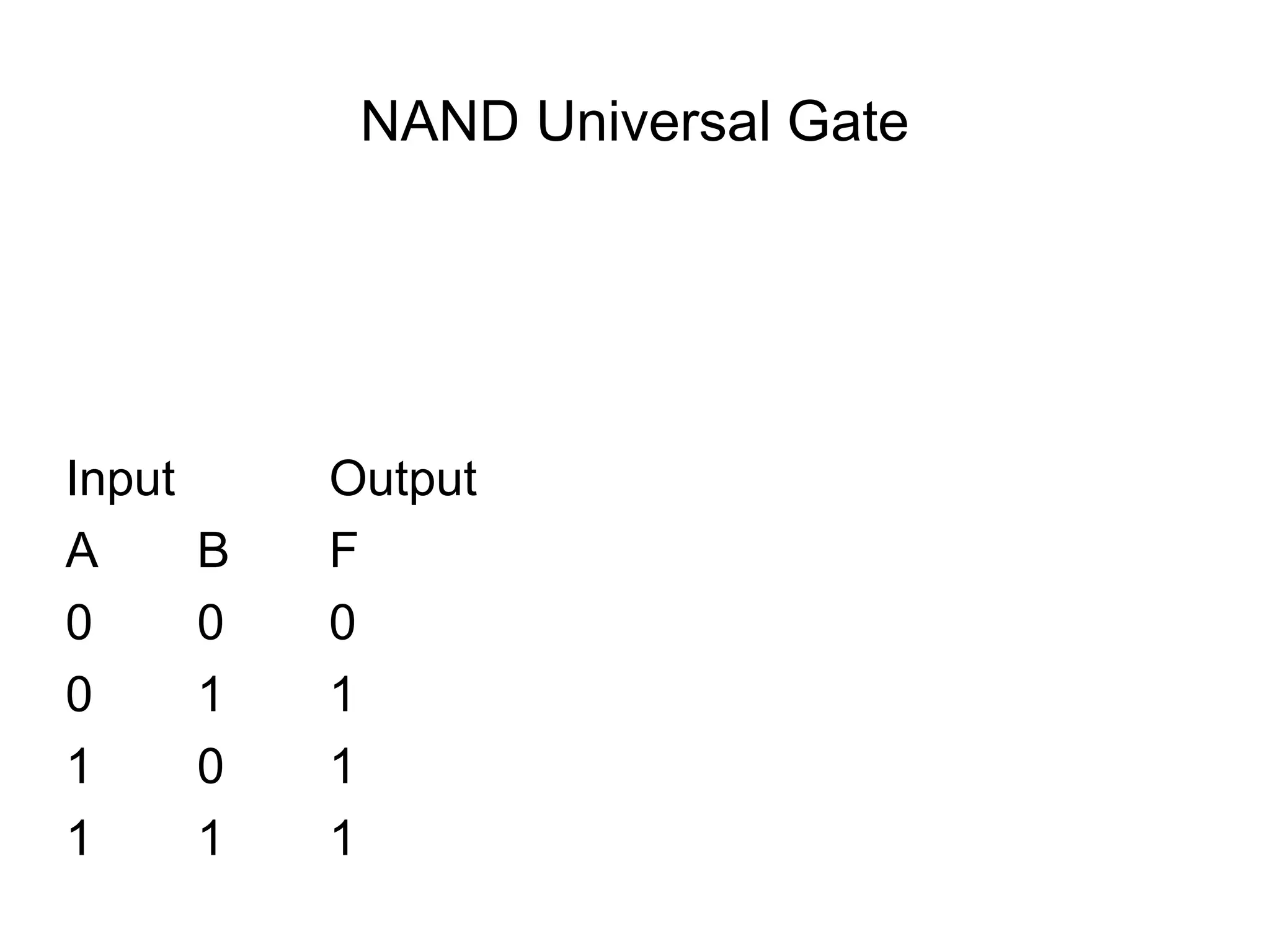
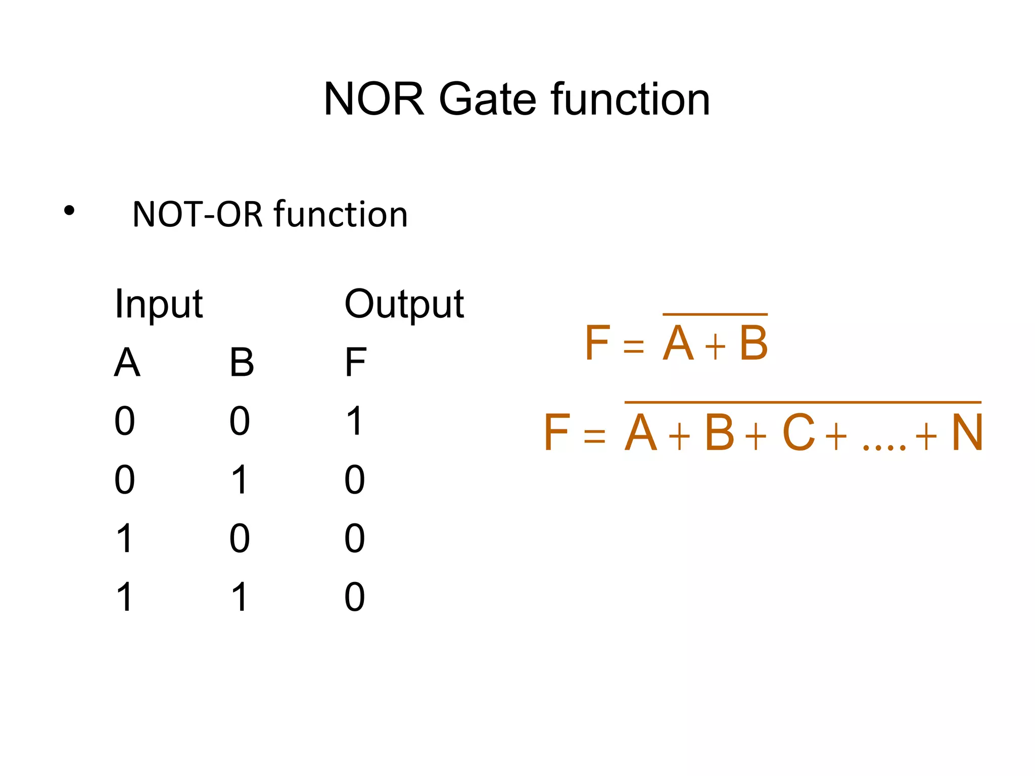
Digital Logic & Design
Lecture 05
Recap
• Octal Number System
• Alternate Representations
– Excess Code
– BCD Code
– Gray Code
• Alphanumeric Code (ASCII)
• Error Detection using Parity Bit
Logic Gates
• Basic Building Blocks
• Logic Gate Symbol
• Unique function
• Truth or Function Table
• Function Expression
• Timing Diagram
AND Gate
• 1 output
• 2 inputs
• 3 inputs
• 4 inputs
• Multiple inputs
AND Gate function
• Logical Multiplication function
Input Output
A B F
0 0 0
0 1 0
1 0 0
1 1 1
BAF •=
NCBAF ••••= ....
AND Gate Timing Diagram
AND Gate function
BAF •=
AND Gate Timing Diagram
BAF •=
OR Gate
• 1 output
• 2 inputs
• 3 inputs
• 4 inputs
• Multiple inputs
OR Gate function
• Boolean Add function
Input Output
A B F
0 0 0
0 1 1
1 0 1
1 1 1
BAF +=
NCBAF ++++= ..
OR Gate Timing Diagram
NOT Gate
• 1 input
• 1 output
NOT Gate function
• Invert function
Input Output
A F
0 1
1 0
AF =
NOT Gate Timing Diagram
AND Gate Applications
• Enable/Disable Device
– Counter counts when it receives pulses
OR Gate Applications
• Car door open alarm
NOT Gate Applications
• 1’s Complement
Alternate Representations
NAND Gate
• 1 output
• 2 inputs
• 3 inputs
• 4 inputs
• Multiple inputs
NAND Gate function
• NOT-AND function
Input Output
A B F
0 0 1
0 1 1
1 0 1
1 1 0
BAF •=
NCBAF ••••= ....
NAND Gate Timing Diagram
t0
t4
t5
t6
t1
t2
t3
A
B
F
NAND Universal Gate
Input Output
A B F
0 0 1
0 1 1
1 0 1
1 1 0
NAND Universal Gate
Input Output Output
A B F1 F
0 0 1 0
0 1 1 0
1 0 1 0
1 1 0 1
NAND Universal Gate
Input Output
A B F
0 0 0
0 1 1
1 0 1
1 1 1
NOR Gate
• 1 output
• 2 inputs
• 3 inputs
• 4 inputs
• Multiple inputs
NOR Gate function
• NOT-OR function
Input Output
A B F
0 0 1
0 1 0
1 0 0
1 1 0
BAF +=
NCBAF ++++= ....
NOR Gate Timing Diagram

Digital logic design DLD Logic gates

Editor's Notes

  • #2 Asalam O Aleikum students. I am Waseem Ikram. This is the fifth lecture in a series of 45 lectures on Digital Logic Design.