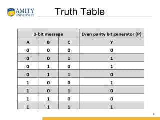
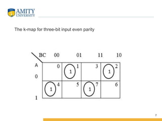
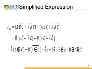
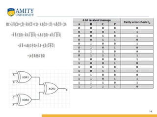
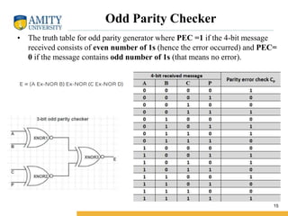
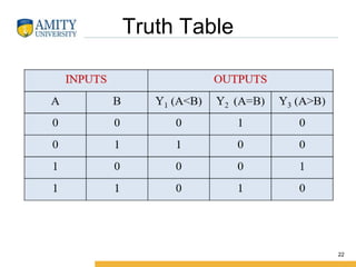
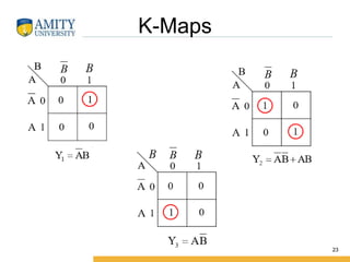
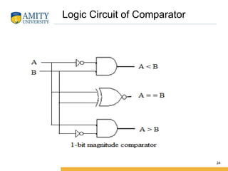
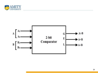
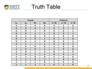
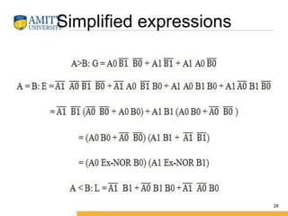
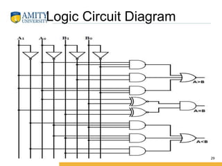
Module I
Digital electronics
Parity circuits and comparators
Parity Bit
• In digital electronic systems, during data transmission and
processing, data gets distorted. This is due to the noises added
to it. Such noises change 0s to 1s and 1s to 0s.
• A parity bit is an extra bit in any binary message to make the
total number of 1’s either odd or even. We need to add the
parity bit to a signal. This is done by the Parity generator. This
parity inclusive binary message then transmits from transmitter
to receiver end.
2
Parity generator and checker
• A parity generator is a combinational logic circuit that
generates the parity bit in the transmitter.
• On the other hand, a circuit that checks the parity in the
receiver is called parity checker.
• The parity generating technique is mostly used in error
detection techniques for the data transmission.
3
4
There are two types of parity circuits
• Even Parity circuit
In even parity bit scheme, the parity bit is ‘0’ if there are even
number of 1s in the data stream and the parity bit is ‘1’ if there
are odd number of 1s in the data stream.
• Odd Parity circuit
In odd parity bit scheme, the parity bit is ‘1’ if there are even
number of 1s in the data stream and the parity bit is ‘0’ if there
are odd number of 1s in the data stream. Let us discuss both even
and odd parity generators.
Type of parity generator circuits
Even Parity Generator
• Let A, B, and C be input bits and Y be output
that is even parity bit. Even parity generates as
a result of the calculation of the number of
ones in the message bit.
• If the number of 1s is even Y gets the value as
0, and if it is odd, then the parity bit Y gets the
value 1. Following is the truth table for 3-bit
even parity generator.
5
Truth Table
6
7
The k-map for three-bit input even parity
Simplified Expression
8
• This circuit is just generating the parity bit. The complete signal
is a combination of the message signal and the parity bit.
9
3 bit Odd Parity Generator
• Let us consider that the 3-bit data is to be transmitted with an odd parity bit.
The three inputs are A, B and C and P is the output parity bit. The total
number of bits must be odd in order to generate the odd parity bit.
10
11
The total number of 1s in the input bits must be odd for the odd parity bit. If
the total number of 1s in input bits is odd, then P gets the value 0, and if it is
even then, P is assigned the value 1.
Parity Checker
• A parity checker is a logical circuit that checks data transmission
errors. Based on the type of parity generated, it can be even a
parity checker or odd parity checker. The number of inputs must
be even for even parity checker and odd for odd parity checker.
If a parity error occurs, the “even” output goes low, and “odd’
output goes high in case of even parity checker. It is the other
way round for odd parity checker.
12
Even Parity Checker
• Consider that three input message along with even parity bit is generated at the
transmitting end. These 4 bits are applied as input to the parity checker circuit
which checks the possibility of error on the data. Since the data is transmitted
with even parity, four bits received at circuit must have an even number of 1s.
• The below table shows the truth table for the even parity checker in which PEC
= 1 if the error occurs, i.e., the four bits received have odd number of 1s and
PEC = 0 if no error occurs, i.e., if the 4-bit message has even number of 1s.
13
14
Odd Parity Checker
• The truth table for odd parity generator where PEC =1 if the 4-bit message
received consists of even number of 1s (hence the error occurred) and PEC=
0 if the message contains odd number of 1s (that means no error).
15
Practice Problem
• Derive a circuit a 3-bit parity generator and
4 bit parity checker.
16
Comparator
17
A digital comparator or magnitude comparator is
a hardware electronic device that takes two
numbers as input in binary form and determines
whether one number is greater than, less than or
equal to the other number. Comparators are used
in central processing unit s (CPUs) and
microcontrollers (MCUs).
Comparator
18
• Identity Comparator
Comparators that have only one output
terminal and produces the output either low or
high are identity comparators.
• Magnitude Comparator
Comparators with three output terminals and
checks for three conditions i.e greater than or
less than or equal to is magnitude comparator.
19
20
1- Bit Magnitude Comparator
• This magnitude comparator has two inputs
A and B
• Three outputs A<B, A=B and A>B.
• This magnitude comparator compares the
two numbers of single bits
21
Truth Table
22
K-Maps
23
Logic Circuit of Comparator
24
2-bit Comparator
• A 2-bit comparator compares two binary
numbers, each of two bits and produces
their relation such as one number is equal
or greater than or less than the other.
25
26
Truth Table
27
Simplified expressions
28
Logic Circuit Diagram
29
30

1.5.1 Lect_parity.pptx

  • 1.
    Module I Digital electronics Paritycircuits and comparators
  • 2.
    Parity Bit • Indigital electronic systems, during data transmission and processing, data gets distorted. This is due to the noises added to it. Such noises change 0s to 1s and 1s to 0s. • A parity bit is an extra bit in any binary message to make the total number of 1’s either odd or even. We need to add the parity bit to a signal. This is done by the Parity generator. This parity inclusive binary message then transmits from transmitter to receiver end. 2
  • 3.
    Parity generator andchecker • A parity generator is a combinational logic circuit that generates the parity bit in the transmitter. • On the other hand, a circuit that checks the parity in the receiver is called parity checker. • The parity generating technique is mostly used in error detection techniques for the data transmission. 3
  • 4.
    4 There are twotypes of parity circuits • Even Parity circuit In even parity bit scheme, the parity bit is ‘0’ if there are even number of 1s in the data stream and the parity bit is ‘1’ if there are odd number of 1s in the data stream. • Odd Parity circuit In odd parity bit scheme, the parity bit is ‘1’ if there are even number of 1s in the data stream and the parity bit is ‘0’ if there are odd number of 1s in the data stream. Let us discuss both even and odd parity generators. Type of parity generator circuits
  • 5.
    Even Parity Generator •Let A, B, and C be input bits and Y be output that is even parity bit. Even parity generates as a result of the calculation of the number of ones in the message bit. • If the number of 1s is even Y gets the value as 0, and if it is odd, then the parity bit Y gets the value 1. Following is the truth table for 3-bit even parity generator. 5
  • 6.
  • 7.
    7 The k-map forthree-bit input even parity
  • 8.
  • 9.
    • This circuitis just generating the parity bit. The complete signal is a combination of the message signal and the parity bit. 9
  • 10.
    3 bit OddParity Generator • Let us consider that the 3-bit data is to be transmitted with an odd parity bit. The three inputs are A, B and C and P is the output parity bit. The total number of bits must be odd in order to generate the odd parity bit. 10
  • 11.
    11 The total numberof 1s in the input bits must be odd for the odd parity bit. If the total number of 1s in input bits is odd, then P gets the value 0, and if it is even then, P is assigned the value 1.
  • 12.
    Parity Checker • Aparity checker is a logical circuit that checks data transmission errors. Based on the type of parity generated, it can be even a parity checker or odd parity checker. The number of inputs must be even for even parity checker and odd for odd parity checker. If a parity error occurs, the “even” output goes low, and “odd’ output goes high in case of even parity checker. It is the other way round for odd parity checker. 12
  • 13.
    Even Parity Checker •Consider that three input message along with even parity bit is generated at the transmitting end. These 4 bits are applied as input to the parity checker circuit which checks the possibility of error on the data. Since the data is transmitted with even parity, four bits received at circuit must have an even number of 1s. • The below table shows the truth table for the even parity checker in which PEC = 1 if the error occurs, i.e., the four bits received have odd number of 1s and PEC = 0 if no error occurs, i.e., if the 4-bit message has even number of 1s. 13
  • 14.
  • 15.
    Odd Parity Checker •The truth table for odd parity generator where PEC =1 if the 4-bit message received consists of even number of 1s (hence the error occurred) and PEC= 0 if the message contains odd number of 1s (that means no error). 15
  • 16.
    Practice Problem • Derivea circuit a 3-bit parity generator and 4 bit parity checker. 16
  • 17.
    Comparator 17 A digital comparatoror magnitude comparator is a hardware electronic device that takes two numbers as input in binary form and determines whether one number is greater than, less than or equal to the other number. Comparators are used in central processing unit s (CPUs) and microcontrollers (MCUs).
  • 18.
  • 19.
    • Identity Comparator Comparatorsthat have only one output terminal and produces the output either low or high are identity comparators. • Magnitude Comparator Comparators with three output terminals and checks for three conditions i.e greater than or less than or equal to is magnitude comparator. 19
  • 20.
  • 21.
    1- Bit MagnitudeComparator • This magnitude comparator has two inputs A and B • Three outputs A<B, A=B and A>B. • This magnitude comparator compares the two numbers of single bits 21
  • 22.
  • 23.
  • 24.
    Logic Circuit ofComparator 24
  • 25.
    2-bit Comparator • A2-bit comparator compares two binary numbers, each of two bits and produces their relation such as one number is equal or greater than or less than the other. 25
  • 26.
  • 27.
  • 28.
  • 29.
  • 30.