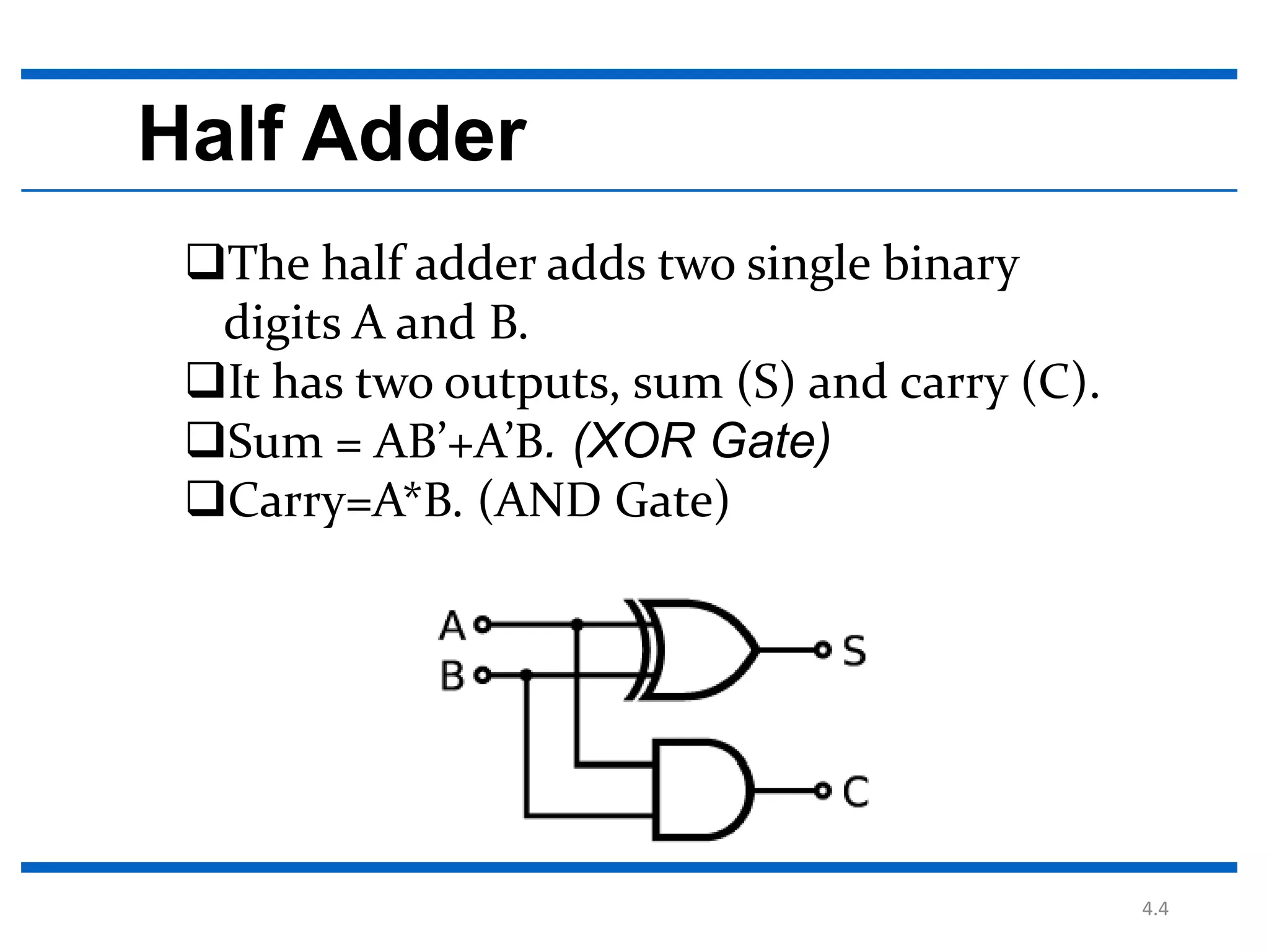
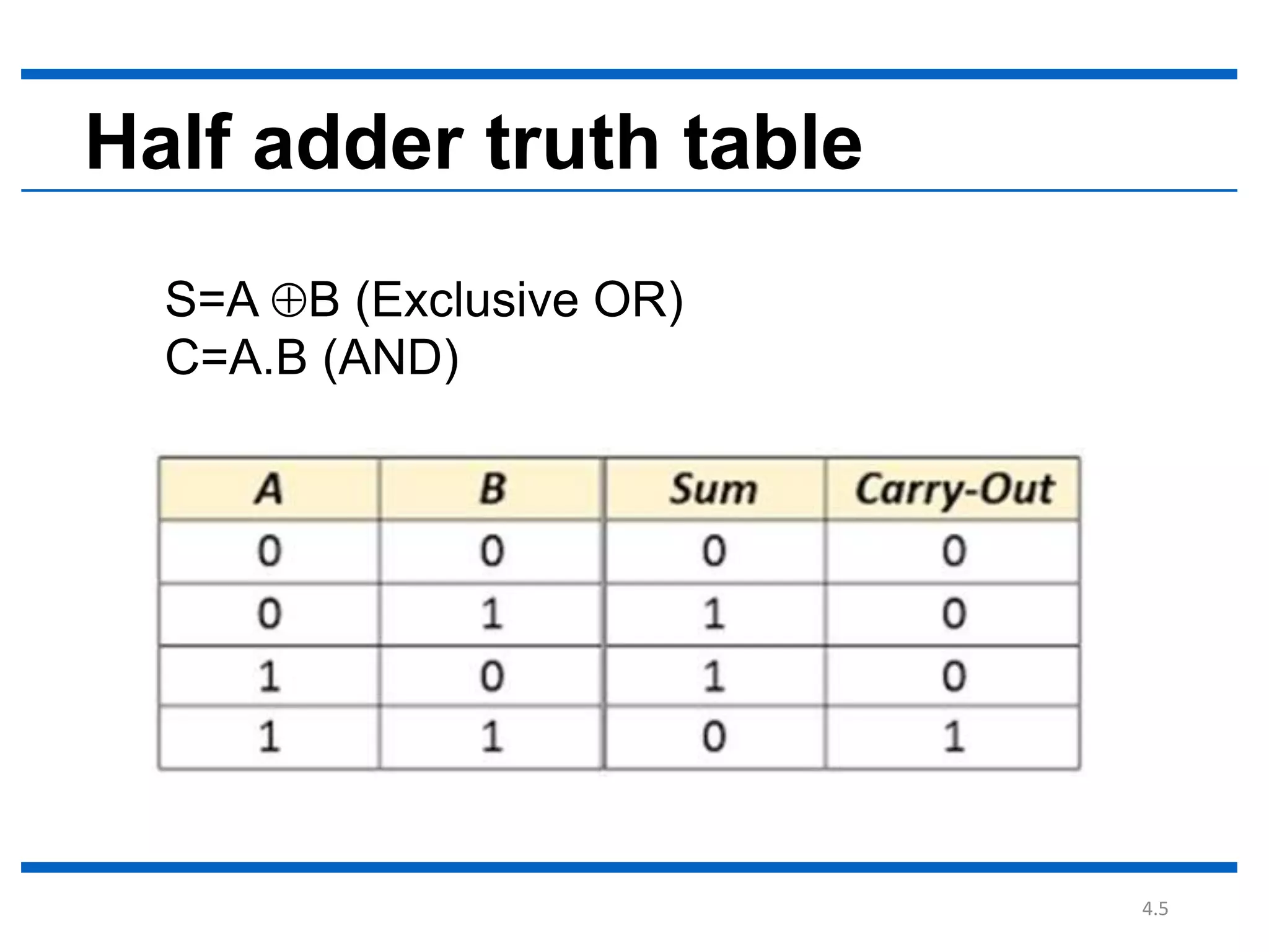
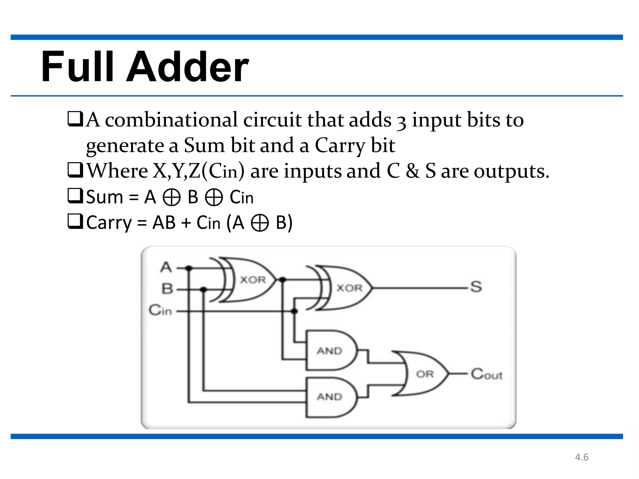
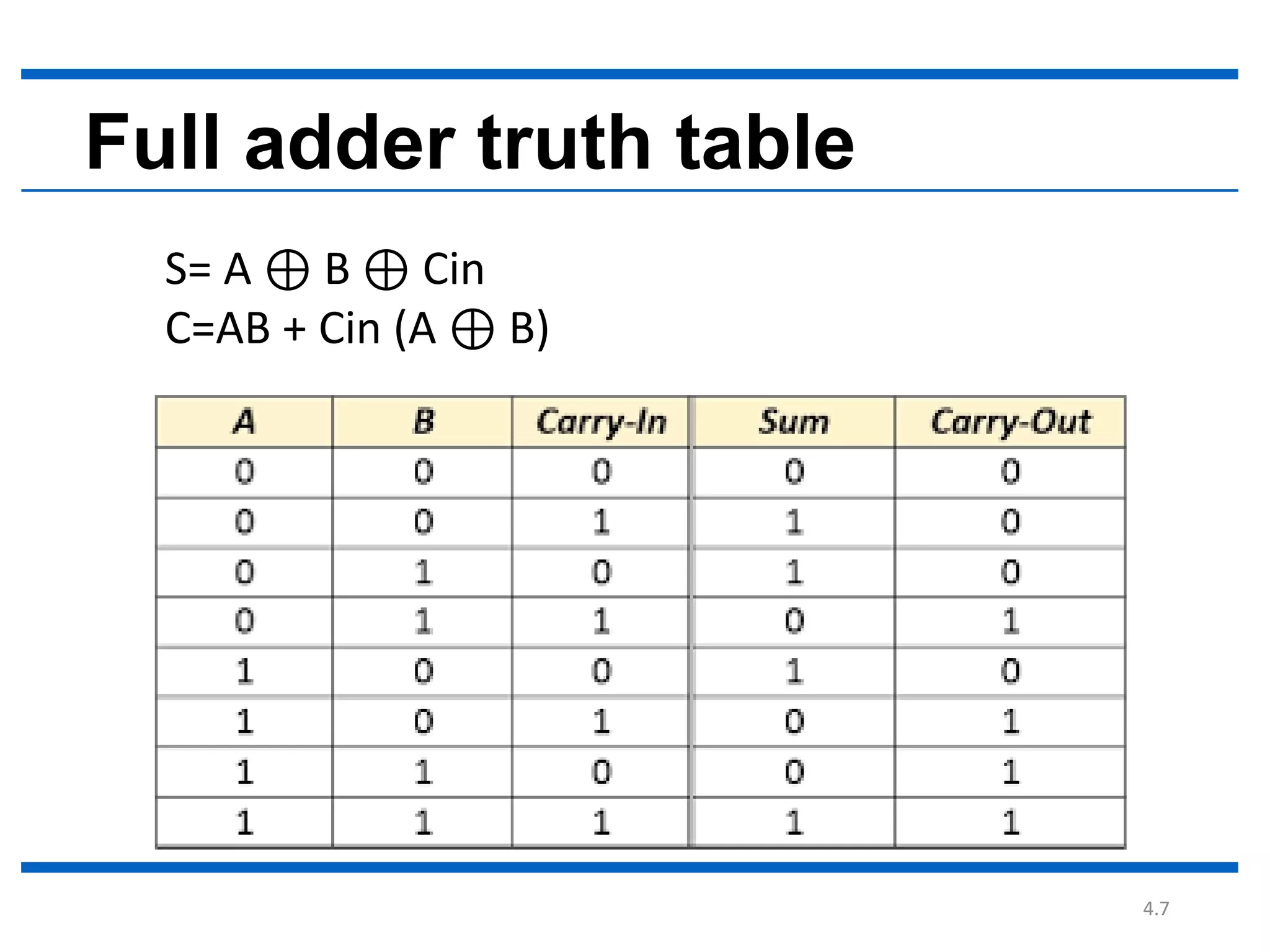
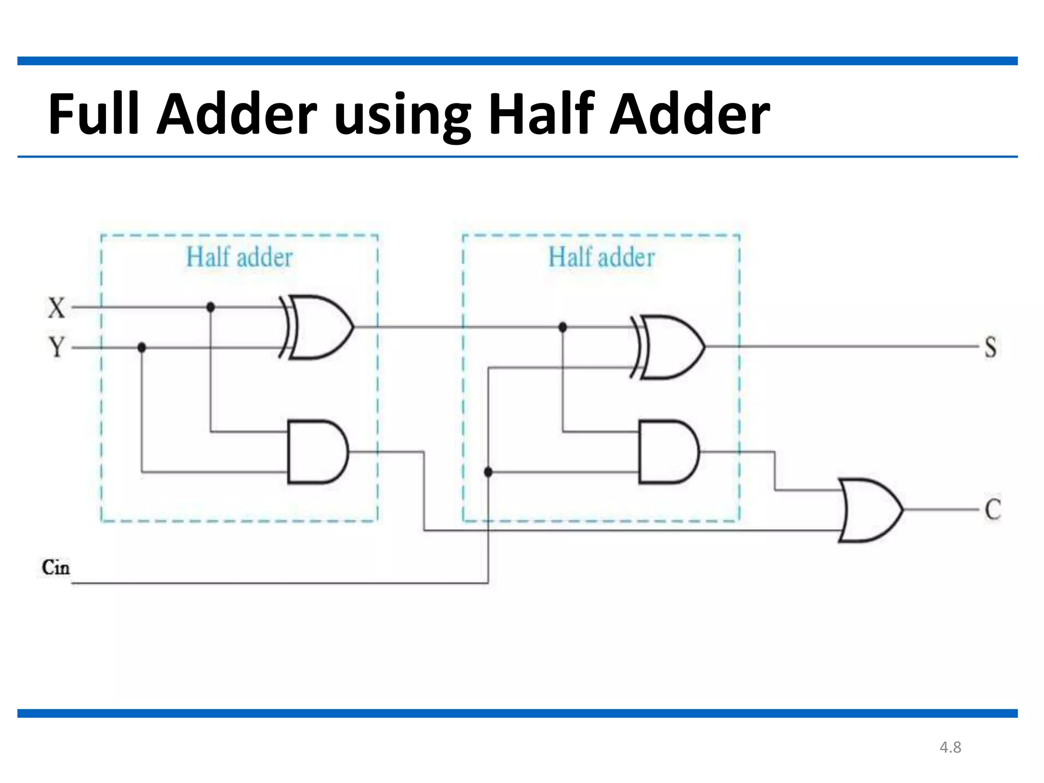
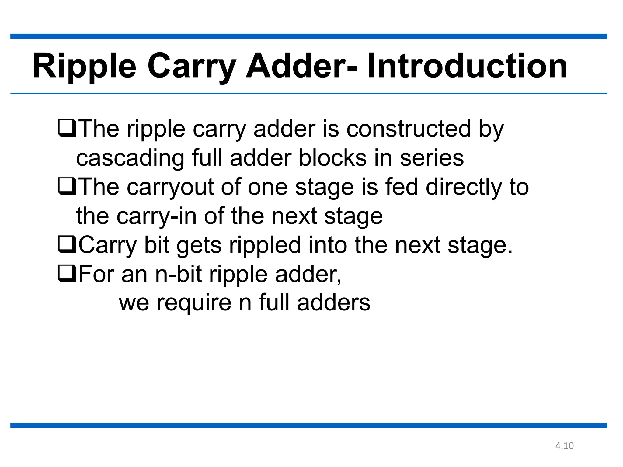
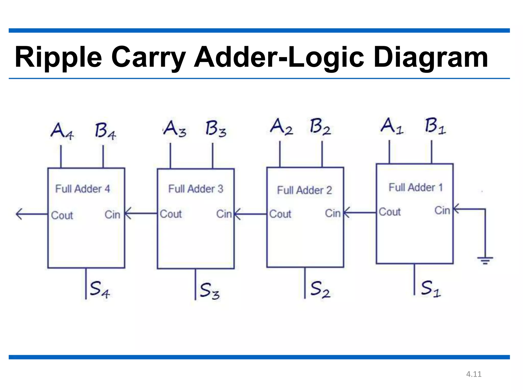
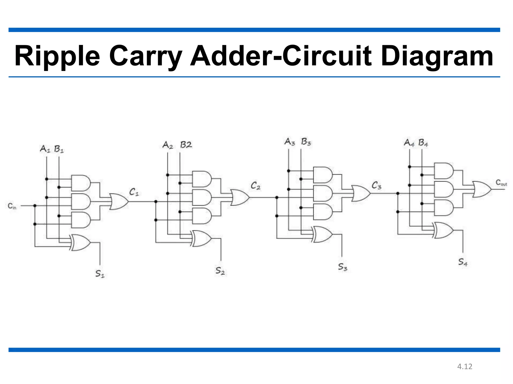
Ripple carry adder, full
adder implementation
using half adder.
By
Md. Fazle Rabbi
16CSE057
4.2
 An adder is a digital circuit that performs
addition of numbers.
 It can be constructed for many numerical
representations, such as binary-coded decimal
 The most common adders operate on binary
numbers.
What is Adder
4.3
Half Adder
Full Adder
Types Of Adder
4.4
The half adder adds two single binary
digits A and B.
It has two outputs, sum (S) and carry (C).
Sum = AB’+A’B. (XOR Gate)
Carry=A*B. (AND Gate)
Half Adder
4.5
Half adder truth table
S=A B (Exclusive OR)
C=A.B (AND)
4.6
A combinational circuit that adds 3 input bits to
generate a Sum bit and a Carry bit
Where X,Y,Z(Cin) are inputs and C & S are outputs.
Sum = A ⊕ B ⊕ Cin
Carry = AB + Cin (A ⊕ B)
Full Adder
4.7
Full adder truth table
S= A ⊕ B ⊕ Cin
C=AB + Cin (A ⊕ B)
4.8
Full Adder using Half Adder
4.9
Ripple Carry Adder
4.10
The ripple carry adder is constructed by
cascading full adder blocks in series
The carryout of one stage is fed directly to
the carry-in of the next stage
Carry bit gets rippled into the next stage.
For an n-bit ripple adder,
we require n full adders
Ripple Carry Adder- Introduction
4.11
Ripple Carry Adder-Logic Diagram
4.12
Ripple Carry Adder-Circuit Diagram
4.13
Ripple Carry Adder-Truth Table
4.14
Ripple Carry Adder-Delay
 A full adder becomes active only when its
carry in is made available by its adjacent less
significant full adder.
 When carry in becomes available to the full
adder, it starts its operation.
 It produces the corresponding output sum bit
and carry bit.
4.15
Thank you

1.ripple carry adder, full adder implementation using half adder.