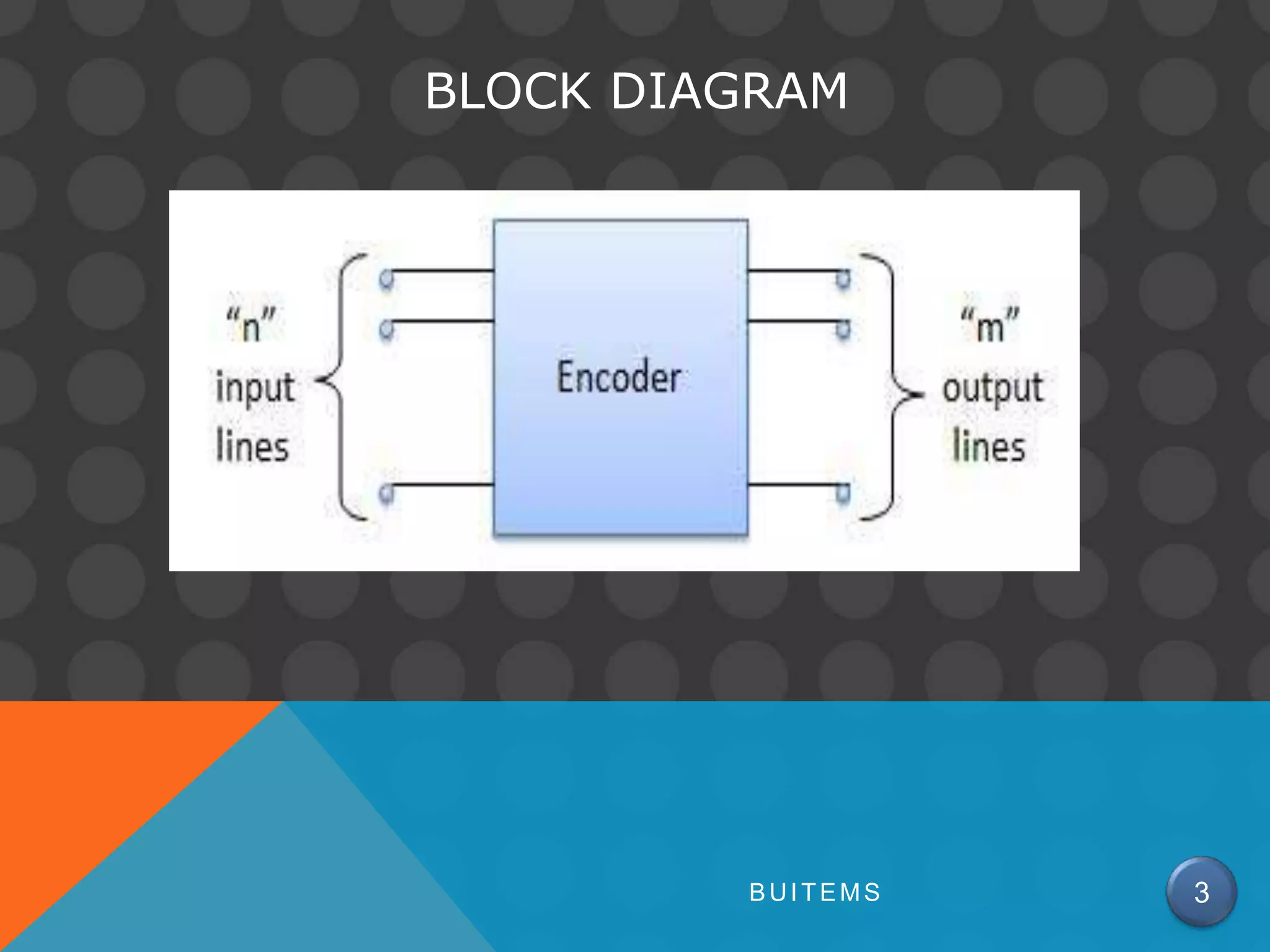
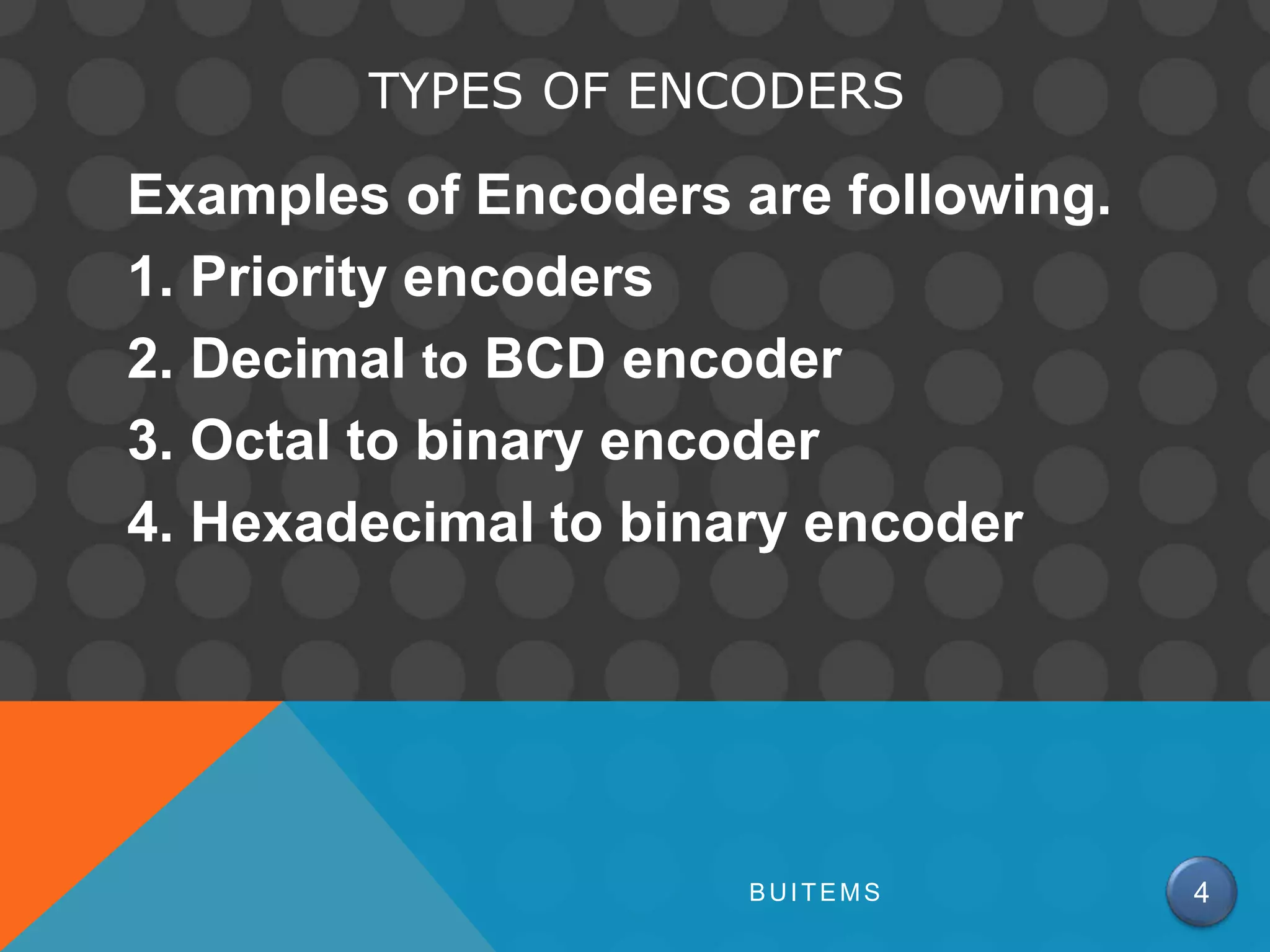
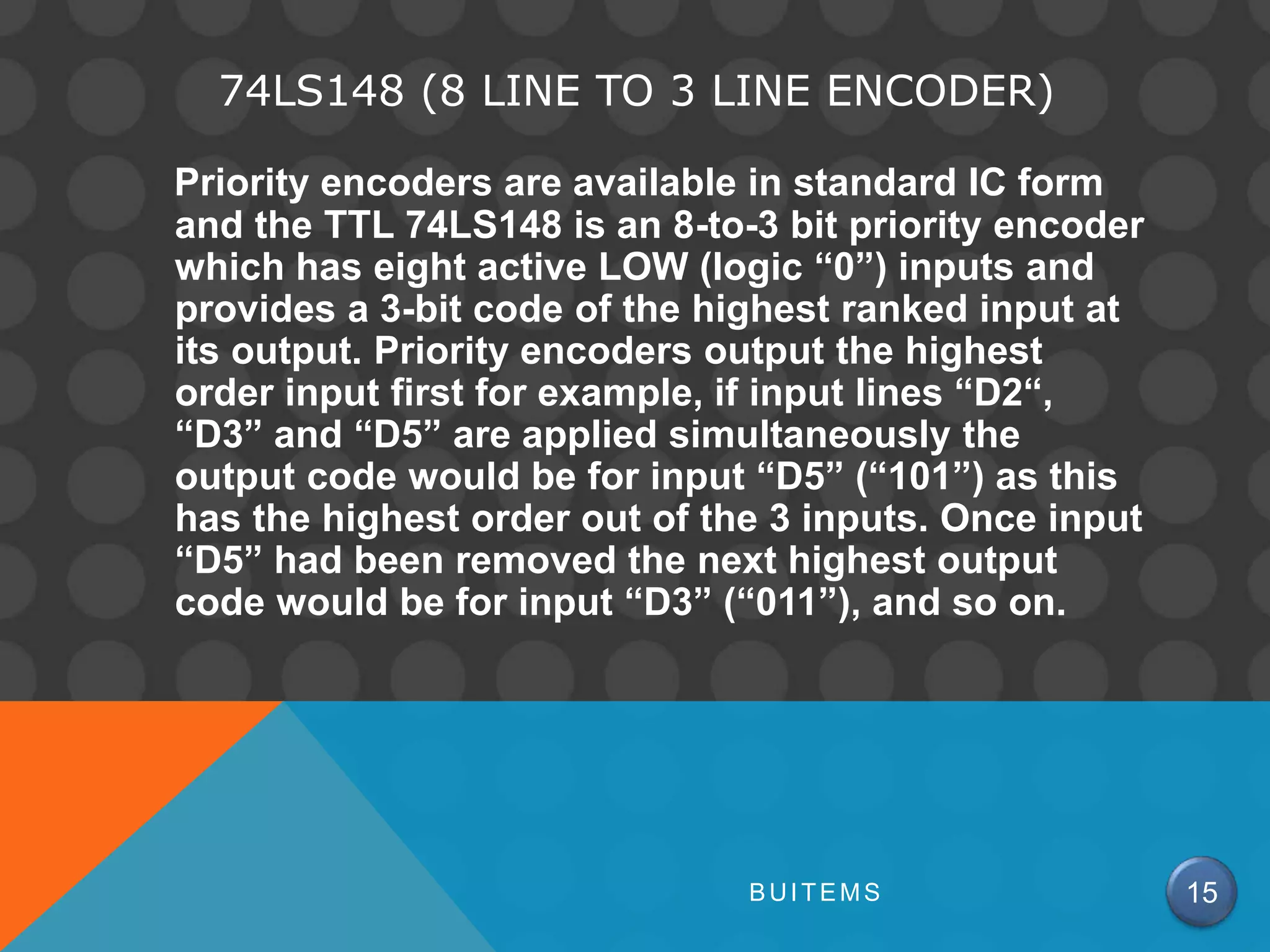
BUITEMS 1
ENCODERS
Encoder is a combinational circuit which is
designed to perform the inverse operation
of the decoder. An encoder has n number of
input lines and m number of output lines.
An encoder produces an m bit binary code
corresponding to the digital input number.
The encoder accepts an n input digital word
and converts it into an m bit another digital
word.
BUITEMS 2
BLOCK DIAGRAM
BUITEMS 3
TYPES OF ENCODERS
Examples of Encoders are following.
1. Priority encoders
2. Decimal to BCD encoder
3. Octal to binary encoder
4. Hexadecimal to binary encoder
BUITEMS 4
PRIORITY ENCODER
This is a special type of encoder. Priority is
given to the input lines. If two or more input line
are 1 at the same time, then the input line with
highest priority will be considered. There are
four input D0, D1, D2, D3 and two output Y0, Y1.
Out of the four input D3 has the highest priority
and D0 has the lowest priority. That means if
D3 = 1 then Y1 Y0 = 11 irrespective of the other
inputs. Similarly if D3 = 0 and D2 = 1 then Y1 Y0 =
10 irrespective of the other inputs.
BUITEMS 5
BLOCK DIAGRAM
BUITEMS 6
TRUTH TABLE
BUITEMS 7
LOGIC CIRCUIT
BUITEMS 8
DECIMAL TO BCD ENCODER
A decimal to BCD encoder has 10 input lines D0 to D9 and
4 output lines Y0 to Y3. Below is the truth table for a
decimal to BCD encoder.
Below boolean functions are formed by ORing all the input
lines for which output is 1. For instance Y0 is 1 for D1, D3,
D5, D7 & D9 input lines.
Y0 = D1 + D3 + D5 + D7 + D9
Y1 = D2 + D3 + D6 + D7
Y2 = D4 + D5 + D6 + D7
Y3 = D8 + D9
The decimal to BCD encoder can therefore be implemented
with OR gates whose inputs are determined directly from
truth table as shown in the image below.
BUITEMS 9
TRUTH TABLE
BUITEMS 10
BLOCK DIAGRAM
BUITEMS 11
CIRCUIT DIAGRAM
BUITEMS 12
LIMITATIONS WITH DECIMAL TO BCD ENCODER
A decimal to BCD encoder has limitations.
1. For 10 bits input, there can be 210 possible
combinations, out of which only 10 are used
using 4 output lines.
2. The discrepancy of 0 output due to all inputs
being 0 or D0 being 0 is resolved by using
additional input known as Enable
3. Only one input can be active at any given time.
BUITEMS 13
74HC147 (DECIMAL TO BCD ENCODER)
BUITEMS 14
74LS148 (8 LINE TO 3 LINE ENCODER)
Priority encoders are available in standard IC form
and the TTL 74LS148 is an 8-to-3 bit priority encoder
which has eight active LOW (logic “0”) inputs and
provides a 3-bit code of the highest ranked input at
its output. Priority encoders output the highest
order input first for example, if input lines “D2“,
“D3” and “D5” are applied simultaneously the
output code would be for input “D5” (“101”) as this
has the highest order out of the 3 inputs. Once input
“D5” had been removed the next highest output
code would be for input “D3” (“011”), and so on.
BUITEMS 15
BLOCK DIAGRAM AND TRUTH TABLE
BUITEMS 16
THE END
BUITEMS 17

Encoder and decoder

  • 1.
  • 2.
    ENCODERS Encoder is acombinational circuit which is designed to perform the inverse operation of the decoder. An encoder has n number of input lines and m number of output lines. An encoder produces an m bit binary code corresponding to the digital input number. The encoder accepts an n input digital word and converts it into an m bit another digital word. BUITEMS 2
  • 3.
  • 4.
    TYPES OF ENCODERS Examplesof Encoders are following. 1. Priority encoders 2. Decimal to BCD encoder 3. Octal to binary encoder 4. Hexadecimal to binary encoder BUITEMS 4
  • 5.
    PRIORITY ENCODER This isa special type of encoder. Priority is given to the input lines. If two or more input line are 1 at the same time, then the input line with highest priority will be considered. There are four input D0, D1, D2, D3 and two output Y0, Y1. Out of the four input D3 has the highest priority and D0 has the lowest priority. That means if D3 = 1 then Y1 Y0 = 11 irrespective of the other inputs. Similarly if D3 = 0 and D2 = 1 then Y1 Y0 = 10 irrespective of the other inputs. BUITEMS 5
  • 6.
  • 7.
  • 8.
  • 9.
    DECIMAL TO BCDENCODER A decimal to BCD encoder has 10 input lines D0 to D9 and 4 output lines Y0 to Y3. Below is the truth table for a decimal to BCD encoder. Below boolean functions are formed by ORing all the input lines for which output is 1. For instance Y0 is 1 for D1, D3, D5, D7 & D9 input lines. Y0 = D1 + D3 + D5 + D7 + D9 Y1 = D2 + D3 + D6 + D7 Y2 = D4 + D5 + D6 + D7 Y3 = D8 + D9 The decimal to BCD encoder can therefore be implemented with OR gates whose inputs are determined directly from truth table as shown in the image below. BUITEMS 9
  • 10.
  • 11.
  • 12.
  • 13.
    LIMITATIONS WITH DECIMALTO BCD ENCODER A decimal to BCD encoder has limitations. 1. For 10 bits input, there can be 210 possible combinations, out of which only 10 are used using 4 output lines. 2. The discrepancy of 0 output due to all inputs being 0 or D0 being 0 is resolved by using additional input known as Enable 3. Only one input can be active at any given time. BUITEMS 13
  • 14.
    74HC147 (DECIMAL TOBCD ENCODER) BUITEMS 14
  • 15.
    74LS148 (8 LINETO 3 LINE ENCODER) Priority encoders are available in standard IC form and the TTL 74LS148 is an 8-to-3 bit priority encoder which has eight active LOW (logic “0”) inputs and provides a 3-bit code of the highest ranked input at its output. Priority encoders output the highest order input first for example, if input lines “D2“, “D3” and “D5” are applied simultaneously the output code would be for input “D5” (“101”) as this has the highest order out of the 3 inputs. Once input “D5” had been removed the next highest output code would be for input “D3” (“011”), and so on. BUITEMS 15
  • 16.
    BLOCK DIAGRAM ANDTRUTH TABLE BUITEMS 16
  • 17.