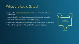
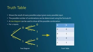
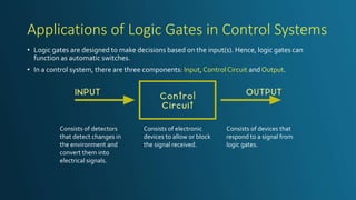
Originally made for a class presentation in SPM Form 5 - Electronics
The logic gate examples are animated. Since GIFs are not supported in SlideShare, the slide can be downloaded from here:
https://drive.google.com/file/d/1Jeuz1Y9hBZCNMp6JXnb5gC73uiHD-GGR/view?usp=sharing
2. What are Logic Gates?
• Logic gates are electronic switches with one or more inputs and one
output only.
• Input is data fed into the processor to perform logical operations.
• The result of the operations is called the output.
• Logic gates operate on a binary input, that is the input is either 0 or 1.
• The output depends on the input and the type of logic gate.
3. Truth Table
• Shows the result of every possible output given every possible input.
• The possible number of combinations can be determined using the formula N2.
• A tree diagram can be used to show all the possible combination.
• For 2 inputs: A B
0 0
0 1
1 0
1 1
Tree Diagram Truth Table
5. NOT Gate
• The output is always opposite to the input.Therefore, a NOT
gate is also called an inverter.
• The inversion by a NOT gate can be written in the Boolean
algebraic expression:
A X
0 1
1 0
AX
6. • The output is 1 if both inputs are 1.
• The Boolean algebraic expression for the action of anAND
gate is:
AND Gate
BAX
*Dot sign representsAND operation.
A B X
0 0 0
0 1 0
1 0 0
1 1 1
7. OR Gate
• The output is 1 if either one or both inputs are 1.
• The Boolean algebraic expression for the action of anOR
gate is:
BAX
*Plus sign represents OR operation.
A B X
0 0 0
0 1 1
1 0 1
1 1 1
9. NAND GATE
• A NAND gate is equivalent to anAND gate followed by a
NOT gate.
• It is clear that the output is 0 if both inputs give an output of
1. In other words, its output is that of an AND gate inverted.
• The Boolean algebraic expression for this gate:
BAx
A B X
0 0 1
0 1 1
1 0 1
1 1 0
10. NOR GATE
• A NOR gate is equivalent to an OR gate folllowed by a NOT
gate.
• It is clear that the output is 1 if both inputs are 0n. Other
combinations of inputs give an output of 0. In other words,
its output is that of an OR gate inverted.
• The Boolean algebraic expression for this gate:
BAx
A B X
0 0 1
0 1 0
1 0 0
1 1 0
16. Applications of Logic Gates in Control Systems
• Logic gates are designed to make decisions based on the input(s). Hence, logic gates can
function as automatic switches.
• In a control system, there are three components: Input, ControlCircuit and Output.
Consists of detectors
that detect changes in
the environment and
convert them into
electrical signals.
Consists of electronic
devices to allow or block
the signal received.
Consists of devices that
respond to a signal from
logic gates.
17. Street Light
• Light sensor at the top of the lamp.
• The light is turned on when little to NO light is present.
• The NOT Gate is used.
18. Smoke Alarm
• The alarm can be activated automatically when smoke is
detected OR an emergency button is pressed.
• The OR Gate is used.