Downloaded 512 times


![Complements
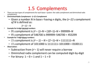
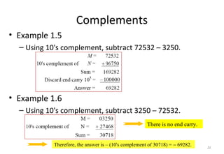
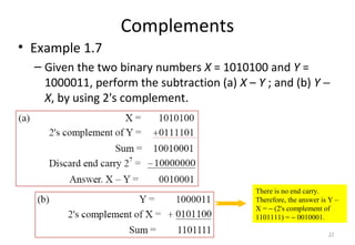
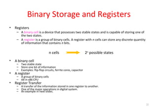
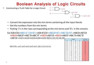
• Radix Complement
• Example: Base-10
• Example: Base-2
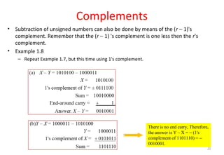
The r's complement of an n-digit number N in base r is defined as
rn
– N for N ≠ 0 and as 0 for N = 0. Comparing with the (r − 1) 's
complement, we note that the r's complement is obtained by adding 1 to the
(r − 1) 's complement, since rn
– N = [(rn
− 1) – N] + 1.
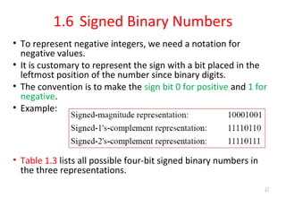
The 10's complement of 012398 is 987602
The 10's complement of 246700 is 753300
The 2's complement of 1101100 is 0010100
The 2's complement of 0110111 is 1001001
31](https://image.slidesharecdn.com/digitallogicdesignpart1-170910142807/85/Digital-logic-design-part1-31-320.jpg)
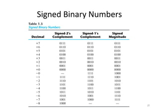
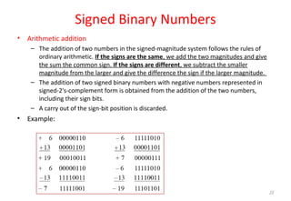
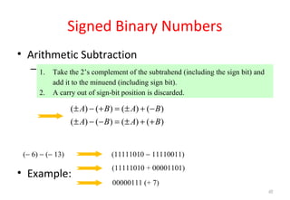
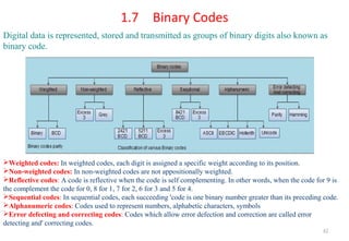


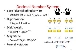
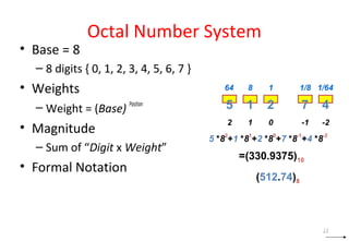
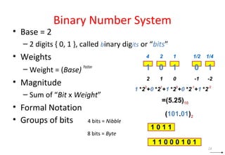
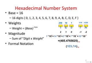
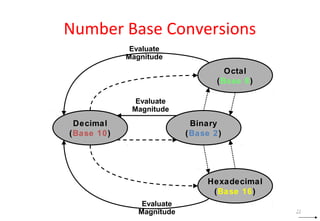
This document discusses digital logic design and binary numbers. It covers topics such as digital vs analog signals, binary number systems, addition and subtraction in binary, and number base conversions between decimal, binary, octal, and hexadecimal. It also discusses complements, specifically 1's complement and radix complement. The purpose is to provide background information on fundamental concepts for digital logic design.