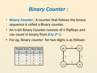
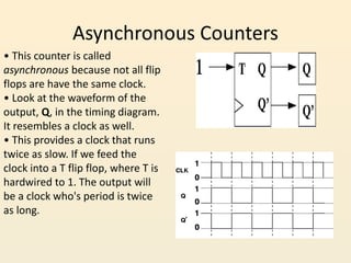
This document discusses different types of counters used in digital circuits. It defines a counter as a sequential circuit that cycles through a sequence of states in response to clock pulses. Binary counters count in binary and can count from 0 to 2n-1 with n flip-flops. Asynchronous counters have flip-flops that are not triggered simultaneously by a clock, while synchronous counters use a common clock for all flip-flops. Other counter types include ring counters, Johnson counters, and decade counters. The document provides examples of binary, asynchronous, and synchronous counters and discusses their applications in areas like timing sequences and addressing memory.
This Presentation is useful to study Digital Electronics subject about D and T Flip-Flop. This Presentation is also useful to make Presentation on Flip-Flop.
The document explains about the concepts of sequential circuits in Digital electronics.
This will be helpful for the beginners in VLSI and electronics students.
These slides contain the basic of sequential logic, and includes a detailed and animated description of Flip-Flop and latches, it includes shift registers and counters also. It covers the fourth unit of Digital Logic Design
Synchronous down counter with full description.
All the flip-flop are clocked simultaneously.
Synchronous counters can operate at much higher frequencies than asynchronous counters.
As clock is simultaneously given to all flip-flops there is no problem of propagation delay. Hence they are high speed counters and are preferred when number of flip-flops increase's in the given design.
In this counter will counter
This presentation is all about counters, focusing on synchronous and asynchronous counters. The unique feature is the incorporation of the circuit images generated from MULTISIM software imparting practical knowledge to the users.
This presentation is all about counters, focusing on asynchronous and synchronous counters. The unique feature is the incorporation of the circuit images generated from MULTI SIM software imparting practical knowledge to the users.
The French Revolution, which began in 1789, was a period of radical social and political upheaval in France. It marked the decline of absolute monarchies, the rise of secular and democratic republics, and the eventual rise of Napoleon Bonaparte. This revolutionary period is crucial in understanding the transition from feudalism to modernity in Europe.
For more information, visit-www.vavaclasses.com
The Art Pastor's Guide to Sabbath | Steve ThomasonSteve Thomason
What is the purpose of the Sabbath Law in the Torah. It is interesting to compare how the context of the law shifts from Exodus to Deuteronomy. Who gets to rest, and why?
Unit 8 - Information and Communication Technology (Paper I).pdfThiyagu K
This slides describes the basic concepts of ICT, basics of Email, Emerging Technology and Digital Initiatives in Education. This presentations aligns with the UGC Paper I syllabus.
Students, digital devices and success - Andreas Schleicher - 27 May 2024..pptxEduSkills OECD
Andreas Schleicher presents at the OECD webinar ‘Digital devices in schools: detrimental distraction or secret to success?’ on 27 May 2024. The presentation was based on findings from PISA 2022 results and the webinar helped launch the PISA in Focus ‘Managing screen time: How to protect and equip students against distraction’ https://www.oecd-ilibrary.org/education/managing-screen-time_7c225af4-en and the OECD Education Policy Perspective ‘Students, digital devices and success’ can be found here - https://oe.cd/il/5yV
How to Split Bills in the Odoo 17 POS ModuleCeline George
Bills have a main role in point of sale procedure. It will help to track sales, handling payments and giving receipts to customers. Bill splitting also has an important role in POS. For example, If some friends come together for dinner and if they want to divide the bill then it is possible by POS bill splitting. This slide will show how to split bills in odoo 17 POS.
We all have good and bad thoughts from time to time and situation to situation. We are bombarded daily with spiraling thoughts(both negative and positive) creating all-consuming feel , making us difficult to manage with associated suffering. Good thoughts are like our Mob Signal (Positive thought) amidst noise(negative thought) in the atmosphere. Negative thoughts like noise outweigh positive thoughts. These thoughts often create unwanted confusion, trouble, stress and frustration in our mind as well as chaos in our physical world. Negative thoughts are also known as “distorted thinking”.
The Roman Empire A Historical Colossus.pdfkaushalkr1407
The Roman Empire, a vast and enduring power, stands as one of history's most remarkable civilizations, leaving an indelible imprint on the world. It emerged from the Roman Republic, transitioning into an imperial powerhouse under the leadership of Augustus Caesar in 27 BCE. This transformation marked the beginning of an era defined by unprecedented territorial expansion, architectural marvels, and profound cultural influence.
The empire's roots lie in the city of Rome, founded, according to legend, by Romulus in 753 BCE. Over centuries, Rome evolved from a small settlement to a formidable republic, characterized by a complex political system with elected officials and checks on power. However, internal strife, class conflicts, and military ambitions paved the way for the end of the Republic. Julius Caesar’s dictatorship and subsequent assassination in 44 BCE created a power vacuum, leading to a civil war. Octavian, later Augustus, emerged victorious, heralding the Roman Empire’s birth.
Under Augustus, the empire experienced the Pax Romana, a 200-year period of relative peace and stability. Augustus reformed the military, established efficient administrative systems, and initiated grand construction projects. The empire's borders expanded, encompassing territories from Britain to Egypt and from Spain to the Euphrates. Roman legions, renowned for their discipline and engineering prowess, secured and maintained these vast territories, building roads, fortifications, and cities that facilitated control and integration.
The Roman Empire’s society was hierarchical, with a rigid class system. At the top were the patricians, wealthy elites who held significant political power. Below them were the plebeians, free citizens with limited political influence, and the vast numbers of slaves who formed the backbone of the economy. The family unit was central, governed by the paterfamilias, the male head who held absolute authority.
Culturally, the Romans were eclectic, absorbing and adapting elements from the civilizations they encountered, particularly the Greeks. Roman art, literature, and philosophy reflected this synthesis, creating a rich cultural tapestry. Latin, the Roman language, became the lingua franca of the Western world, influencing numerous modern languages.
Roman architecture and engineering achievements were monumental. They perfected the arch, vault, and dome, constructing enduring structures like the Colosseum, Pantheon, and aqueducts. These engineering marvels not only showcased Roman ingenuity but also served practical purposes, from public entertainment to water supply.
2. Definition:
• Counter : A sequential circuit that goes through prescribed
sequence of states upon the application of clock pulse is
called a counter.
• The input pulses are called count pulses, may be clock pulses
or they may originate from an external source or occur at
prescribed intervals or at random.
• In a counter the sequence of states may follow binary count
or any other sequence.
• Counters are found in almost all equipment containing digital
system
3. Binary Counter :
• Binary Counter : A counter that follows the binary
sequence is called a Binary counter.
• An n-bit Binary Counter consists of n flipflops and
can count in binary from 0 to 2n-1.
• For eg. Binary counter for two digits is as follows:
Present State Next State
A B A B
0 0 0 1
0 1 1 0
1 0 1 1
1 1 0 0
00 01
1011
1
11
1
4. Example of binary counter
00 01
1011
0
0
0
10 1
1
1
Present State Inputs Next State
Q1 Q0 X Q1 Q0
0 0 0 0 1
0 0 1 1 1
0 1 0 1 0
0 1 1 0 0
1 0 0 1 1
1 0 1 0 1
1 1 0 0 0
1 1 1 1 0
• Here’s the another example for binary counter and its state
table:
5. Applications of Counters
• Some of the applications of counters in a
sequential circuits are as follows:
To count the number of occurances
Generating Timing sequences
Count up or down
Increment or decrement count
Sequence events
Divide frequency
Address memory
As temporary memory
6. Two principal categories
• Counters are divided in two categories, these
are:
– Asynchronous (Ripple) Counters - the first flip-flop
is clocked by the external clock pulse, and then
each successive flip-flop is clocked by the Q or Q'
output of the previous flip-flop.
– Synchronous Counters - all memory elements are
simultaneously triggered by the same clock.
7. Few other categories of counters:
• Apart from synchronous and asynchronous
counters which are the major ones the other
types of counters are as follows:
–Ring counter
–Johnson counter
–Decade counter
–Up–down counter
8. Asynchronous Counters:
• Here flipflop output transition serves as a source for
triggering other flipflops.
• This means that that the clockpulse is provided to a
single flipflop
• The change of state of a given flipflop is dependent
on the states of other flipflops.
• In other words the flipflops are not triggered by
simultanous clock pulses but the transitions in other
flipflops.
9. Asynchronous Counters
• This counter is called
asynchronous because not all flip
flops are have the same clock.
• Look at the waveform of the
output, Q, in the timing diagram.
It resembles a clock as well.
• This provides a clock that runs
twice as slow. If we feed the
clock into a T flip flop, where T is
hardwired to 1. The output will
be a clock who's period is twice
as long.
10. Two-bit asynchronous counter
• The external clock is
connected to the clock
input of the first flip-flop
only.
• So, it changes state at the
negative edge of each
clock pulse, but the next
flipflop changes only
when triggered by the
negative edge of the Q
output of the first one.
11. Two-bit asynchronous counter
• Because of the inherent
propagation delay through a
flip-flop, the transition of
the input clock pulse and a
transition of the Q output of
FF0 can never occur at
exactly the same time.
• Therefore, the flip-flops
cannot be triggered
simultaneously, producing
an asynchronous operation.
• Eg : As shown, there is some
small delay between the
CLK, Q0 and Q1 transitions.
12. Two-bit asynchronous counter
• Usually, all the CLEAR inputs are connected together,
so that a single pulse can clear all the flip-flops
before counting starts.
• The 2-bit ripple counter circuit above has four
different states, each one corresponding to a count
value.
• Similarly, a counter with n flip-flops can have 2N
states.
• The number of states in a counter is known as its
mod (modulo) number.
13. Two-bit asynchronous counter
• Thus a 2-bit counter is a
mod-4 counter.
• This is because the
most significant flip-flop
produces one pulse for
every n pulses at the
clock input of the least
significant flip-flop .
.
14. 3 bit asynchronous “ripple” counter
using T flip flops
• This is called as a ripple
counter due to the way the
FFs respond one after
another in a kind of
rippling effect.
15. Synchronous Counters
• To eliminate the "ripple" effects, use a common clock for each flip-
flop and a combinational circuit to generate the next state.
• For an up-counter,
use an incrementer =>
D3 Q3
D2 Q2
D1 Q1
D0 Q0
Clock
Incre-
menter
A3
A2
A1
A0
S3
S2
S1
S0
16. Synchronous Counters
• To eliminate the "ripple" effects, use a common clock
for each flip-flop and a combinational circuit to
generate the next state.
• Hence the counters in which all the flipflops are
provided with a clock pulse simultanously are called
the Synchronous counters.
• Synchronous counters may be of the following types
– Up counter
– Down counter
17. • Internal details =>
• Internal Logic
– XOR complements each bit
– AND chain causes complement
of a bit if all bits toward LSB
from it equal 1
• Count Enable
– Forces all outputs of AND
chain to 0 to “hold” the state
• Carry Out
– Added as part of incrementer
– Connect to Count Enable of
additional 4-bit counters to
form larger counters
Synchronous Counters (continued)
Incrementer
18. Design Example: Synchronous BCD
• Use the sequential logic model to design a synchronous BCD counter with
D flip-flops
• State Table =>
• Input combinations
1010 through 1111
are don’t cares
Current State
Q8 Q4 Q2 Q1
Next State
Q8 Q4 Q2 Q1
0 0 0 0 0 0 0 1
0 0 0 1 0 0 1 0
0 0 1 0 0 0 1 1
0 0 1 1 0 1 0 0
0 1 0 0 0 1 0 1
0 1 0 1 0 1 1 0
0 1 1 0 0 1 1 1
0 1 1 1 1 0 0 0
1 0 0 0 1 0 0 1
1 0 0 1 0 0 0 0
19. Synchronous BCD (continued)
• Use K-Maps to two-level optimize the next state
equations and manipulate into forms containing XOR
gates:
D1 = Q1’
• D2 = Q2 + Q1Q8’
D4 = Q4 + Q1Q2
D8 = Q8 + (Q1Q8 + Q1Q2Q4)
• Y = Q1Q8
• The logic diagram can be drawn from these equations
– An asynchronous or synchronous reset should be added
20. Synchronous BCD (continued)
• There are chances that
counter is perturbed by a
power disturbance or other
interference and it enters a
state other than 0000
through 1001.
• Find the actual values of the
six next states for the don’t
care combinations from the
equations
• Find the overall state
diagram to assess behavior
for the don’t care states
(states in decimal)
. Present State Next State
Q8 Q4 Q2 Q1 Q8 Q4 Q2 Q1
1 0 1 0 1 0 1 1
1 0 1 1 0 1 1 0
1 1 0 0 1 1 0 1
1 1 0 1 0 1 0 0
1 1 1 0 1 1 1 1
1 1 1 1 0 0 1 0
21. Unused states
• The examples shown so
far have all had 2n
states,
and used n flip-flops. But
sometimes you may have
unused, leftover states.
• For example, here is a
state table and diagram
for a counter that
repeatedly counts from 0
(000) to 5 (101).
• But there are also the
unused states in the state
table.
. Present State Next State
Q2 Q1 Q0 Q2 Q1 Q0
0 0 0 0 0 1
0 0 1 0 1 0
0 1 0 0 1 1
0 1 1 1 0 0
1 0 0 1 0 1
1 0 1 0 0 0
1 1 0 ? ? ?
1 1 1 ? ? ?
001
010
011
100
101
000
22. Unused states can be don’t cares…
• To get the simplest possible
circuit, one can fill in don’t
cares for the next states.
This will also result in don’t
cares for the flip-flop inputs,
which can simplify the
hardware.
• If the circuit somehow ends
up in one of the unused
states (110 or 111), its
behavior will depend on
exactly what the don’t cares
were filled in with.
.
Present State Next State
Q2 Q1 Q0 Q2 Q1 Q0
0 0 0 0 0 1
0 0 1 0 1 0
0 1 0 0 1 1
0 1 1 1 0 0
1 0 0 1 0 1
1 0 1 0 0 0
1 1 0 x x x
1 1 1 x x x
001
010
011
100
101
000
23. Other possibility
• To get the safest possible
circuit, you can explicitly
fill in next states for the
unused states 110 and
111.
• This guarantees that even
if the circuit somehow
enters an unused state, it
will eventually end up in a
valid state.
• This is called a self-
starting counter.
.Present State Next State
Q2 Q1 Q0 Q2 Q1 Q0
0 0 0 0 0 1
0 0 1 0 1 0
0 1 0 0 1 1
0 1 1 1 0 0
1 0 0 1 0 1
1 0 1 0 0 0
1 1 0 0 0 0
1 1 1 0 0 0
001
010
011
100
101
000
111110
24. Ring counters are implemented as shown where output of a flipflop is
given as an input to the next flipflop except the last one. Here the
normal output of the last flipflop is connected back to the input of the
first one. Hence it is called Ring counter.
Ring Counter
25. Johnson Counter
The Johnson counter, also known as the twisted-ring counter,
is exactly the same as the ring counter except that the inverted
output of the last flip-flop is connected to the input of the first
flip-flop.
If it starts from 000, 100, 110, 111, 011 and 001, and the
sequence is repeated so long as there is input pulse.