Download as PDF, PPTX

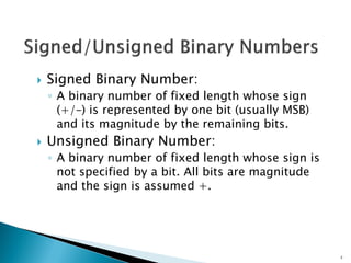
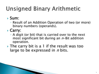
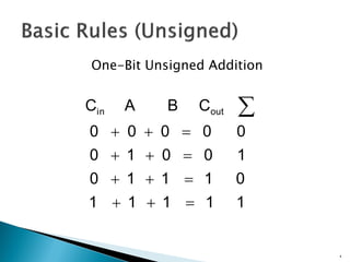
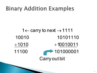

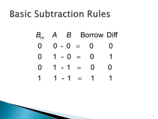
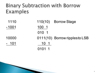
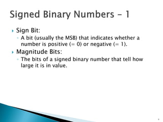
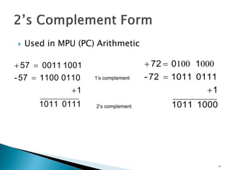
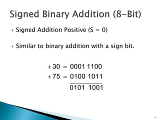
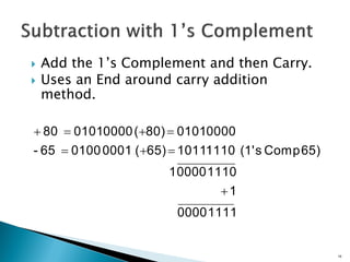
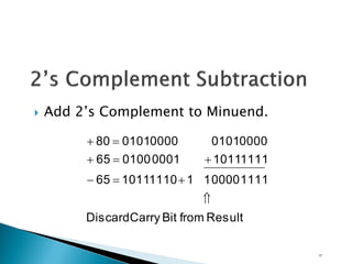
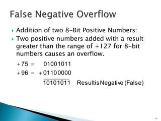
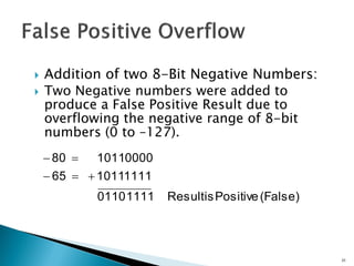
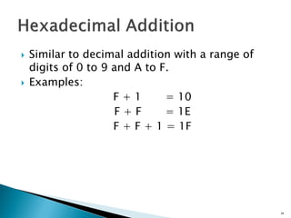
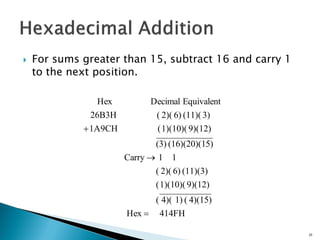
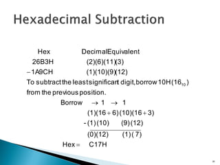
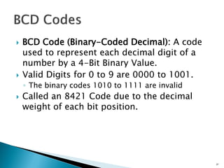
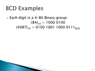
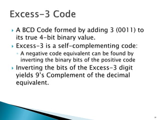
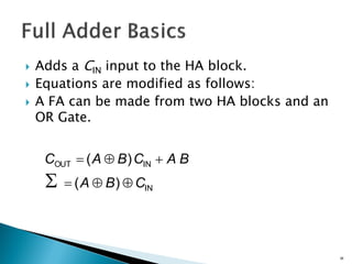
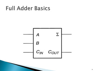
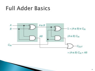
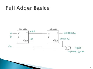
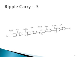
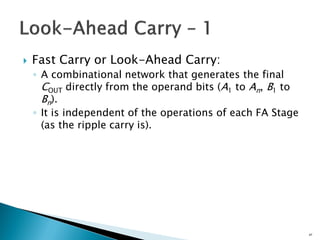
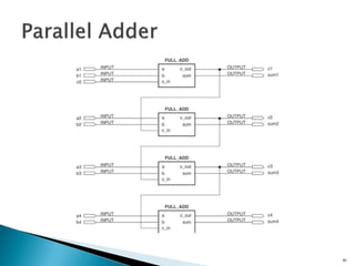
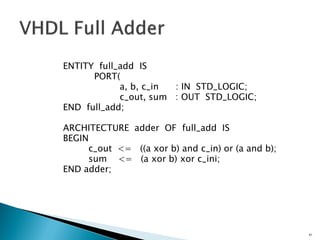
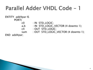
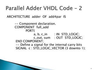
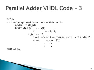
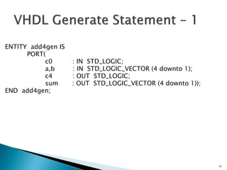
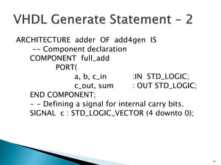
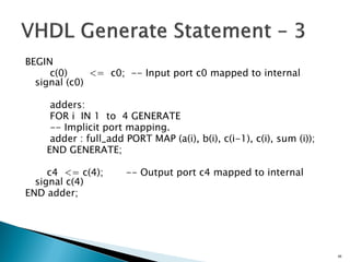
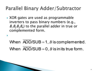
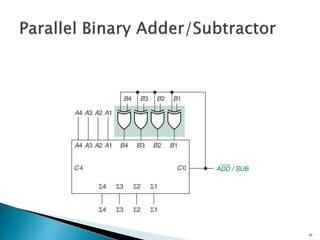
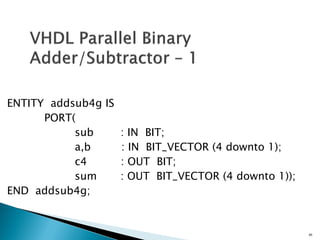
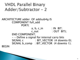
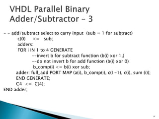
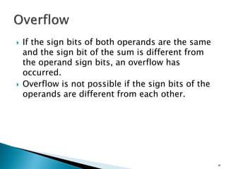
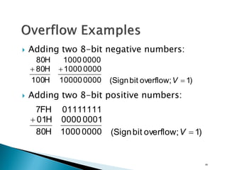
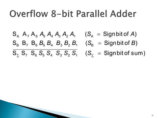
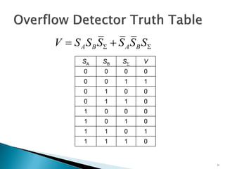
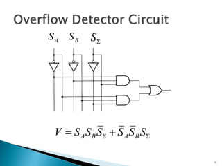
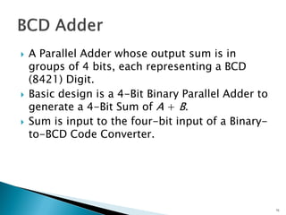
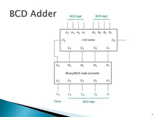

This document discusses digital arithmetic and arithmetic circuits. It covers topics such as signed and unsigned binary numbers, addition, subtraction, overflow, binary-coded decimal codes, and the implementation of adders using full adders in VHDL. Specifically, it defines common digital arithmetic concepts like carries, sums, overflow, and binary number representations. It also describes half adders, full adders, ripple carry adders, and how to construct multi-bit adders using full adder components in VHDL.