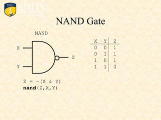
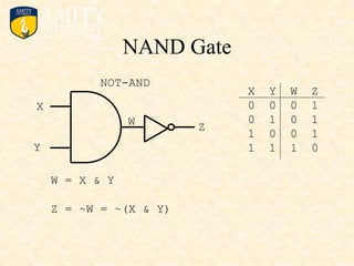
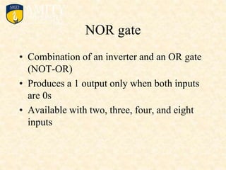
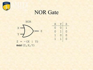
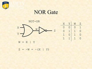
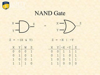
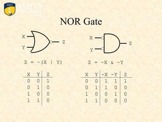
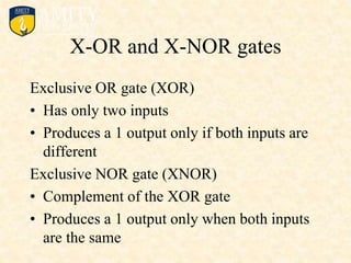
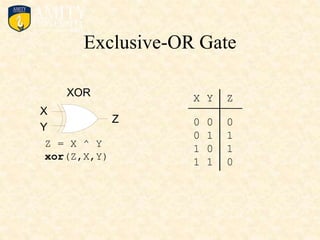
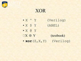
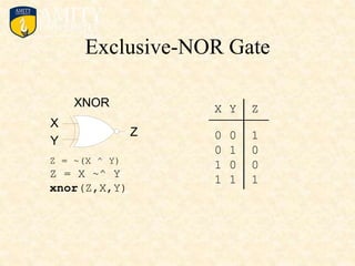
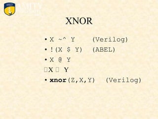
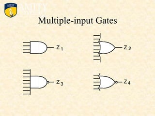
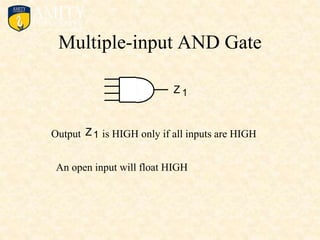
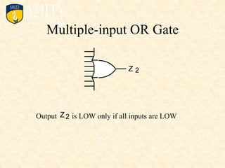
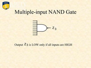
Digital Electronics & Computer
Organization Lab
Syllabus
• Simulation using ORCAD
• To simulate Half Adder circuit
• To simulate Full Adder Circuit
• To simulate the logical part of a simple Arithmetic logical Unit
• To simulate a 4-bit binary adder-subtractor circuit
• Simulation of one digit BCD Adder.
• To simulate and study the tristate buffer
• To simulate the common bus using tri-state buffers and decoder
• To simulate the common bus using multiplexers.
• Study of 8085Microprocessor
• Study of instruction set of 8085
Basic Logic Gates
Basic Logic Gates
and Basic Digital Design
• NOT, AND, and OR Gates
• NAND and NOR Gates
• Exclusive-OR (XOR) Gate
• Multiple-input Gates
NOT gate
• Referred to as an inverter
• Converts the input state to an opposite
output state
• Only two input combinations possible
NOT Gate -- Inverter
X Y
0
1
1
0
X Y
Y
NOT
X Y
Y = ~X
NOT
• Y = ~X (Verilog)
• Y = !X (ABEL)
• Y = not X (VHDL)
• Y = X’
• Y = X
• Y = X (textook)
• not(Y,X) (Verilog)
NOT
NOT
X ~X ~~X = X
X ~X ~~X
0 1 0
1 0 1
AND gate
• Two or more inputs and a single output
• Produces a 1 output only when all inputs are
1s
• Total number of possible combinations: N =
2power(n) where: n = total number of input
variables
• Performs basic operation of multiplication
AND Gate
AND
X
Y
Z
Z = X & Y
X Y Z
0 0 0
0 1 0
1 0 0
1 1 1
• X & Y (Verilog and ABEL)
• X and Y (VHDL)
• X Y
• X Y
• X * Y
• XY (textbook)
• and(Z,X,Y) (Verilog)
AND
U
V
OR gate
• Produces a 1 output if any of its inputs are
1s
• Performs basic operation of addition
• Can have any number of inputs greater than
one
OR Gate
OR
X
Y
Z
Z = X | Y
X Y Z
0 0 0
0 1 1
1 0 1
1 1 1
OR
• X | Y (Verilog)
• X # Y (ABEL)
• X or Y (VHDL)
• X + Y (textbook)
• X V Y
• X U Y
• or(Z,X,Y) (Verilog)
NAND gate
• Combination of an inverter and an AND
gate (NOT-AND)
• Most commonly used logic function
• Produces a 1 output when any of the inputs
are 0s
• Available with two, three, four, eight, and
thirteen inputs
NAND Gate
NAND
X
Y
Z
X Y Z
0 0 1
0 1 1
1 0 1
1 1 0
Z = ~(X & Y)
nand(Z,X,Y)
NAND Gate
NOT-AND
X
Y
Z
W = X & Y
Z = ~W = ~(X & Y)
X Y W Z
0 0 0 1
0 1 0 1
1 0 0 1
1 1 1 0
W
NOR gate
• Combination of an inverter and an OR gate
(NOT-OR)
• Produces a 1 output only when both inputs
are 0s
• Available with two, three, four, and eight
inputs
NOR Gate
NOR
X
Y
Z
X Y Z
0 0 1
0 1 0
1 0 0
1 1 0
Z = ~(X | Y)
nor(Z,X,Y)
NOR Gate
NOT-OR
X
Y
W = X | Y
Z = ~W = ~(X | Y)
X Y W Z
0 0 0 1
0 1 1 0
1 0 1 0
1 1 1 0
Z
W
NAND Gate
X
Y
X
Y
Z Z
Z = ~(X & Y) Z = ~X | ~Y
=
X Y W Z
0 0 0 1
0 1 0 1
1 0 0 1
1 1 1 0
X Y ~X ~Y Z
0 0 1 1 1
0 1 1 0 1
1 0 0 1 1
1 1 0 0 0
NOR Gate
X
Y
Z
Z = ~(X | Y)
X Y Z
0 0 1
0 1 0
1 0 0
1 1 0
X
Y
Z
Z = ~X & ~Y
X Y ~X ~Y Z
0 0 1 1 1
0 1 1 0 0
1 0 0 1 0
1 1 0 0 0
X-OR and X-NOR gates
Exclusive OR gate (XOR)
• Has only two inputs
• Produces a 1 output only if both inputs are
different
Exclusive NOR gate (XNOR)
• Complement of the XOR gate
• Produces a 1 output only when both inputs
are the same
Exclusive-OR Gate
X Y Z
XOR
X
Y
Z 0 0 0
0 1 1
1 0 1
1 1 0
Z = X ^ Y
xor(Z,X,Y)
XOR
• X ^ Y (Verilog)
• X $ Y (ABEL)
• X @ Y
• xor(Z,X,Y) (Verilog)
X Y (textbook)

Exclusive-NOR Gate
X Y Z
XNOR
X
Y
Z 0 0 1
0 1 0
1 0 0
1 1 1
Z = ~(X ^ Y)
Z = X ~^ Y
xnor(Z,X,Y)
XNOR
• X ~^ Y (Verilog)
• !(X $ Y) (ABEL)
• X @ Y
• xnor(Z,X,Y) (Verilog)
X Y
Multiple-input Gates
Z 1 2
3 4
Z Z
Z
Multiple-input AND Gate
Z 1
Output is HIGH only if all inputs are HIGH
Z1
An open input will float HIGH
Multiple-input OR Gate
Output is LOW only if all inputs are LOW
Z2
2
Z
Multiple-input NAND Gate
Output is LOW only if all inputs are HIGH
Z3
3
Z
Multiple-input NOR Gate
Output is HIGH only if all inputs are LOW
Z4
4
Z
Summary
• An AND gate produces a 1 output when all
of its inputs are 1s
• An OR gate produces a 1 output if any of its
inputs are 1s
• A NOT gate converts the input state to an
opposite output state
• A NAND gate produces a 1 output when
any of the inputs are 0s
Summary
• A NOR gate produces a 1 output only when
both inputs are 0s
• An exclusive OR (XOR) gate produces a 1
output only if both inputs are different
• An exclusive NOR (XNOR) gate produces
a 1 output only when both inputs are the
same
Any Questions?

lab1_basic logic gates.ppt

  • 1.
    Digital Electronics &Computer Organization Lab
  • 2.
    Syllabus • Simulation usingORCAD • To simulate Half Adder circuit • To simulate Full Adder Circuit • To simulate the logical part of a simple Arithmetic logical Unit • To simulate a 4-bit binary adder-subtractor circuit • Simulation of one digit BCD Adder. • To simulate and study the tristate buffer • To simulate the common bus using tri-state buffers and decoder • To simulate the common bus using multiplexers. • Study of 8085Microprocessor • Study of instruction set of 8085
  • 3.
  • 4.
    Basic Logic Gates andBasic Digital Design • NOT, AND, and OR Gates • NAND and NOR Gates • Exclusive-OR (XOR) Gate • Multiple-input Gates
  • 5.
    NOT gate • Referredto as an inverter • Converts the input state to an opposite output state • Only two input combinations possible
  • 6.
    NOT Gate --Inverter X Y 0 1 1 0 X Y Y NOT X Y Y = ~X NOT
  • 7.
    • Y =~X (Verilog) • Y = !X (ABEL) • Y = not X (VHDL) • Y = X’ • Y = X • Y = X (textook) • not(Y,X) (Verilog) NOT
  • 8.
    NOT X ~X ~~X= X X ~X ~~X 0 1 0 1 0 1
  • 9.
    AND gate • Twoor more inputs and a single output • Produces a 1 output only when all inputs are 1s • Total number of possible combinations: N = 2power(n) where: n = total number of input variables • Performs basic operation of multiplication
  • 10.
    AND Gate AND X Y Z Z =X & Y X Y Z 0 0 0 0 1 0 1 0 0 1 1 1
  • 11.
    • X &Y (Verilog and ABEL) • X and Y (VHDL) • X Y • X Y • X * Y • XY (textbook) • and(Z,X,Y) (Verilog) AND U V
  • 12.
    OR gate • Producesa 1 output if any of its inputs are 1s • Performs basic operation of addition • Can have any number of inputs greater than one
  • 13.
    OR Gate OR X Y Z Z =X | Y X Y Z 0 0 0 0 1 1 1 0 1 1 1 1
  • 14.
    OR • X |Y (Verilog) • X # Y (ABEL) • X or Y (VHDL) • X + Y (textbook) • X V Y • X U Y • or(Z,X,Y) (Verilog)
  • 15.
    NAND gate • Combinationof an inverter and an AND gate (NOT-AND) • Most commonly used logic function • Produces a 1 output when any of the inputs are 0s • Available with two, three, four, eight, and thirteen inputs
  • 16.
    NAND Gate NAND X Y Z X YZ 0 0 1 0 1 1 1 0 1 1 1 0 Z = ~(X & Y) nand(Z,X,Y)
  • 17.
    NAND Gate NOT-AND X Y Z W =X & Y Z = ~W = ~(X & Y) X Y W Z 0 0 0 1 0 1 0 1 1 0 0 1 1 1 1 0 W
  • 18.
    NOR gate • Combinationof an inverter and an OR gate (NOT-OR) • Produces a 1 output only when both inputs are 0s • Available with two, three, four, and eight inputs
  • 19.
    NOR Gate NOR X Y Z X YZ 0 0 1 0 1 0 1 0 0 1 1 0 Z = ~(X | Y) nor(Z,X,Y)
  • 20.
    NOR Gate NOT-OR X Y W =X | Y Z = ~W = ~(X | Y) X Y W Z 0 0 0 1 0 1 1 0 1 0 1 0 1 1 1 0 Z W
  • 21.
    NAND Gate X Y X Y Z Z Z= ~(X & Y) Z = ~X | ~Y = X Y W Z 0 0 0 1 0 1 0 1 1 0 0 1 1 1 1 0 X Y ~X ~Y Z 0 0 1 1 1 0 1 1 0 1 1 0 0 1 1 1 1 0 0 0
  • 22.
    NOR Gate X Y Z Z =~(X | Y) X Y Z 0 0 1 0 1 0 1 0 0 1 1 0 X Y Z Z = ~X & ~Y X Y ~X ~Y Z 0 0 1 1 1 0 1 1 0 0 1 0 0 1 0 1 1 0 0 0
  • 23.
    X-OR and X-NORgates Exclusive OR gate (XOR) • Has only two inputs • Produces a 1 output only if both inputs are different Exclusive NOR gate (XNOR) • Complement of the XOR gate • Produces a 1 output only when both inputs are the same
  • 24.
    Exclusive-OR Gate X YZ XOR X Y Z 0 0 0 0 1 1 1 0 1 1 1 0 Z = X ^ Y xor(Z,X,Y)
  • 25.
    XOR • X ^Y (Verilog) • X $ Y (ABEL) • X @ Y • xor(Z,X,Y) (Verilog) X Y (textbook) 
  • 26.
    Exclusive-NOR Gate X YZ XNOR X Y Z 0 0 1 0 1 0 1 0 0 1 1 1 Z = ~(X ^ Y) Z = X ~^ Y xnor(Z,X,Y)
  • 27.
    XNOR • X ~^Y (Verilog) • !(X $ Y) (ABEL) • X @ Y • xnor(Z,X,Y) (Verilog) X Y
  • 28.
  • 29.
    Multiple-input AND Gate Z1 Output is HIGH only if all inputs are HIGH Z1 An open input will float HIGH
  • 30.
    Multiple-input OR Gate Outputis LOW only if all inputs are LOW Z2 2 Z
  • 31.
    Multiple-input NAND Gate Outputis LOW only if all inputs are HIGH Z3 3 Z
  • 32.
    Multiple-input NOR Gate Outputis HIGH only if all inputs are LOW Z4 4 Z
  • 33.
    Summary • An ANDgate produces a 1 output when all of its inputs are 1s • An OR gate produces a 1 output if any of its inputs are 1s • A NOT gate converts the input state to an opposite output state • A NAND gate produces a 1 output when any of the inputs are 0s
  • 34.
    Summary • A NORgate produces a 1 output only when both inputs are 0s • An exclusive OR (XOR) gate produces a 1 output only if both inputs are different • An exclusive NOR (XNOR) gate produces a 1 output only when both inputs are the same
  • 35.