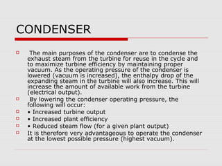
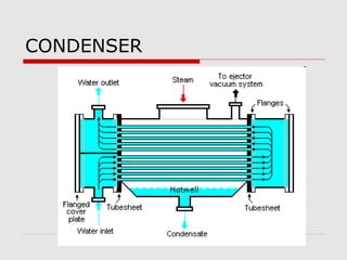
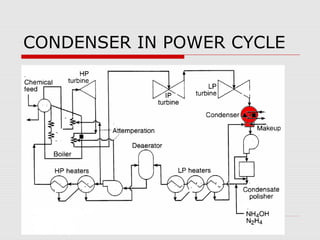
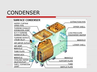
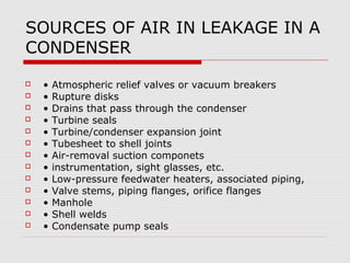
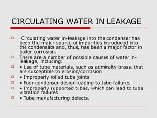
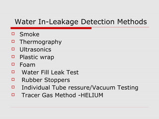
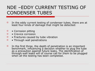
CONDENSER
IN THERMAL POWER PLANTS


      SHIVAJI CHOUDHURY
RANKINE CYCLE
   The Rankine cycle used in modern power plants has
    many more components, but the four components
    are common to all power plants.
    In this cycle, water is heated in the steam generator
    to produce high temperature and pressure steam.
   This steam is then expanded in a turbine to produce
    electricity from a generator that is connected to the
    turbine.
   The steam from the turbine is then condensed back
    into water in the condenser.
    The pump then returns the water to the steam
    generator.
RANKINE CYCLE
                   1-2:CEP WORK
                   2-3:LP HEATING
                   3-4:BFP WORK
                   4-5:HP HEATING
                   5-6:ECO,WW
                   6-7:SUPERHEATING
                   7-8:HPT WORK
                   8-9:REHEAT
                   9-10:IPT WORK
                   10-11:LPT WORK
                   11-1: CONDENSATING
CONDENSER
    The main purposes of the condenser are to condense the
    exhaust steam from the turbine for reuse in the cycle and
    to maximize turbine efficiency by maintaining proper
    vacuum. As the operating pressure of the condenser is
    lowered (vacuum is increased), the enthalpy drop of the
    expanding steam in the turbine will also increase. This will
    increase the amount of available work from the turbine
    (electrical output).
    By lowering the condenser operating pressure, the
    following will occur:
   • Increased turbine output
   • Increased plant efficiency
   • Reduced steam flow (for a given plant output)
   It is therefore very advantageous to operate the condenser
    at the lowest possible pressure (highest vacuum).
FUNCTION OF CONDENSER
     Function of the condenser is to create a vacuum by
    condensing steam,
    Removing dissolved noncondensable gases from the
    condensate
    Conserving the condensate for re-use as the feedwater
    supply to the steam generator
    Providing a leak-tight barrier between the high grade
    condensate contained within the shell and the untreated
    cooling water
    Providing a leak-tight barrier against air ingress,
    preventing excess back pressure on the turbine
    Serving as a drain receptacle, receiving vapor and
    condensate from various other plant heat exchangers,
    steam dumps, and turbine bleed-offs
    receptacle for adding DM makeup
CONDENSER
CONDENSER OPERATION
   The main heat transfer mechanisms in a surface
    condenser are the condensing of saturated steam on
    the outside of the tubes and the heating of the
    circulating water inside the tubes.
   Thus for a given circulating water flow rate, the water
    inlet temperature to the condenser determines the
    operating pressure of the condenser. As this
    temperature is decreased, the condenser pressure will
    also decrease. As described above, this decrease in
    the pressure will increase the plant output and
    efficiency.
   The noncondensable gases consist of mostly air that
    has leaked into the cycle .
   These gases must be vented from the condenser .
REASON FOR REMOVING AIR/GAS

   • The gases will increase the operating pressure of
    the condenser. This rise in pressure will decrease the
    turbine output and efficiency.
   • The gases will blanket the outer surface of the
    tubes. This will severely decrease the heat transfer of
    the steam to the circulating water. Again, the
    pressure in the condenser will increase.
   • The corrosiveness of the condensate in the
    condenser increases as the oxygen content increases.
    Oxygen causes corrosion, mostly in the steam
    generator. Thus, these gases must be removed in
    order to extend the life of cycle components.
CONDENSER TUBE MATERIALS
   Copper based alloy(ASTM B 111,B543)
   Stainless steel (ASTM A268, B268, A249, A213,
    A269)
   Titanium( ASTM B 338 Gr 1&2)
   Carbon steel (ASTM A 179,A214)
CONDENSER IN POWER CYCLE
CONDENSER (500 MW)
CONDENSER
CONDENSER ASSOCIATED EQUIPMENTS

     .1 LP Turbine / condenser                .6 Pressure relief device:
      expansion provisions:                   (rupture disc) (atmospheric relief
    (Spring supported) (expansion               valve)
       joint) (solid mounted)                  .7 Vacuum breaker valve
      .2 Turbine / condenser expansion         Actuated (manual) (electric
       joint:                                   motor) (pneumatic)
     (rubber) (stainless steel)                .8 Instrumentation
      .3 Provisions for feed water            .9 Water box accessories:
       heaters located in transition           Circulating water expansion joints
       section:                                 (rubber arch type)
           (Supports) (Closing plates)         Gauge glasses
       (Lagging)
                                               Cathodic protection
      .4 LP Turbine extraction:
                                                Continuous tube cleaning system
      Pipes: (Lagging) (Supports)
       (Expansion joints)                      Priming system
      .5 Air removal equipment:              Air release valves
     (vacuum pumps) (steam jet air
       ejectors) (hybrid pump / ejector
       system)
Condenser diagnostics flow chart
Effect of Air Ingress
    For maximum thermal efficiency, corresponding to a
     minimum back pressure, a vacuum is maintained in the
     condenser. However, this vacuum encourages air in-
     leakage.
    Thus, to keep the concentration of noncondensable gases as
     low as possible, the condenser system must be leak tight,
     together with any part of the condensate system that is
     under vacuum. Failure to prevent or remove the
     noncondensable gases may cause serious corrosion in the
     system, lower heat transfer properties, and/or increase
     plant heat rate due to the back pressure rise associated
     with a high in leakage.
    The cost of excess back pressure in terms of additional fuel
     or increased heat rate .
    An adequate air-removal and monitoring system is
     essential.
SOURCES OF AIR IN LEAKAGE IN A
CONDENSER
   •   Atmospheric relief valves or vacuum breakers
   •   Rupture disks
   •   Drains that pass through the condenser
   •   Turbine seals
   •   Turbine/condenser expansion joint
   •   Tubesheet to shell joints
   •   Air-removal suction componets
   •   instrumentation, sight glasses, etc.
   •   Low-pressure feedwater heaters, associated piping,
   •   Valve stems, piping flanges, orifice flanges
   •   Manhole
   •   Shell welds
   •   Condensate pump seals
CIRCULATING WATER IN LEAKAGE

    Circulating water in-leakage into the condenser has
    been the major source of impurities introduced into
    the condensate and, thus, has been a major factor in
    boiler corrosion.
   There are a number of possible causes of water in-
    leakage, including:
   • Use of tube materials, such as admiralty brass, that
    are susceptible to erosion/corrosion
   • Improperly rolled tube joints
   • Poor condenser design leading to tube failures.
   • Improperly supported tubes, which can lead to tube
    vibration failures
   • Tube manufacturing defects.
Water In-Leakage Detection Methods
   Smoke
   Thermography
   Ultrasonics
   Plastic wrap
   Foam
    Water Fill Leak Test
    Rubber Stoppers
    Individual Tube ressure/Vacuum Testing
    Tracer Gas Method -HELIUM
NDE –EDDY CURRENT TESTING OF
CONDENSER TUBES
   In the eddy current testing of condenser tubes, there are at
    least four kinds of damage that might be detected:

   •   Corrosion pitting
   •   Crevice corrosion
   •   Fractures caused by tube vibration
   •   Through wall penetrations

   In the first three, the depth of penetration is an important
    benchmark, influencing a decision whether to plug the tube
    as a precaution against future leaks. The identification of
    through-wall leaks will of course call for them to be plugged
    when all the testing has been completed.
CONDENSER TUBE CLEANING
   Macro-fouling (accumulation of debris), not only reduces
    the cooling water flow rate through the tubes it can
    cause tube corrosion and tube erosion failures.
    Micro-fouling (biological growth) and scaling reduces the
    heat transfer coefficient and could cause under deposit
    corrosion resulting in premature tube failures.
   Various tube cleaning options are available to reduce or
    eliminate the micro/macro fouling and scaling.
       off-line
      on-line methods. — (Sponge balls or brushes may be
    automatically recirculated through the condenser)
Cycle Isolation
   Generating plants often suffer from power losses/heat
    rate due to leakages through valves to condenser.

   Check incoming drain lines, feedwater heater high level
    dumps, minimum flow valves, and steam traps for
    leakage or improper operation which could add
    unexpected heat load to the condenser.

   To minimize leakages through valves to condenser ,
    Select all control valves (e g emergency drain of
    heaters) to condenser with leakage class v and Select
    all isolating /drain valve to condenser with leakage class
    MSS SP 61.
CONDENSER DESIGN CRITERIA
    The steam condensing plant shall be designed,
    manufactured and tested as per HEI (latest edition).
   The condenser(s) shall be designed for heat load
    corresponding to unit operation for valves wide open (VWO)
    conditions, 3% make-up, design condenser pressure .
   The value of design condenser pressure to be measured at
    300 mm above the top row of condenser tubes shall be
    guaranteed under VWO condition, 3% make-up, design CW
    inlet temperature and CW flow.The condenser vacuum shall
    be measured with a vacuum grid utilising ASME basket tips.
    The condenser hotwell shall be sized for three (3) minute
    storage capacity (between normal and low-low level).
    Maximum oxygen content of condensate leaving the
    condenser shall be 0.015 cc per litre over 50-100% load
    range.
CONDENSER ( 500 MW )
STANDARDS
   ASME PTC 12.2 -Steam surface
    condensers
   HEI - Standards for steam surface
    condensers
   TEMA.
THANKING YOU

Condenser in thermal power plants

  • 1.
    CONDENSER IN THERMAL POWERPLANTS SHIVAJI CHOUDHURY
  • 2.
    RANKINE CYCLE  The Rankine cycle used in modern power plants has many more components, but the four components are common to all power plants.  In this cycle, water is heated in the steam generator to produce high temperature and pressure steam.  This steam is then expanded in a turbine to produce electricity from a generator that is connected to the turbine.  The steam from the turbine is then condensed back into water in the condenser.  The pump then returns the water to the steam generator.
  • 3.
    RANKINE CYCLE  1-2:CEP WORK  2-3:LP HEATING  3-4:BFP WORK  4-5:HP HEATING  5-6:ECO,WW  6-7:SUPERHEATING  7-8:HPT WORK  8-9:REHEAT  9-10:IPT WORK  10-11:LPT WORK  11-1: CONDENSATING
  • 4.
    CONDENSER  The main purposes of the condenser are to condense the exhaust steam from the turbine for reuse in the cycle and to maximize turbine efficiency by maintaining proper vacuum. As the operating pressure of the condenser is lowered (vacuum is increased), the enthalpy drop of the expanding steam in the turbine will also increase. This will increase the amount of available work from the turbine (electrical output).  By lowering the condenser operating pressure, the following will occur:  • Increased turbine output  • Increased plant efficiency  • Reduced steam flow (for a given plant output)  It is therefore very advantageous to operate the condenser at the lowest possible pressure (highest vacuum).
  • 5.
    FUNCTION OF CONDENSER  Function of the condenser is to create a vacuum by condensing steam,  Removing dissolved noncondensable gases from the condensate  Conserving the condensate for re-use as the feedwater supply to the steam generator  Providing a leak-tight barrier between the high grade condensate contained within the shell and the untreated cooling water  Providing a leak-tight barrier against air ingress, preventing excess back pressure on the turbine  Serving as a drain receptacle, receiving vapor and condensate from various other plant heat exchangers, steam dumps, and turbine bleed-offs  receptacle for adding DM makeup
  • 6.
  • 7.
    CONDENSER OPERATION  The main heat transfer mechanisms in a surface condenser are the condensing of saturated steam on the outside of the tubes and the heating of the circulating water inside the tubes.  Thus for a given circulating water flow rate, the water inlet temperature to the condenser determines the operating pressure of the condenser. As this temperature is decreased, the condenser pressure will also decrease. As described above, this decrease in the pressure will increase the plant output and efficiency.  The noncondensable gases consist of mostly air that has leaked into the cycle .  These gases must be vented from the condenser .
  • 8.
    REASON FOR REMOVINGAIR/GAS  • The gases will increase the operating pressure of the condenser. This rise in pressure will decrease the turbine output and efficiency.  • The gases will blanket the outer surface of the tubes. This will severely decrease the heat transfer of the steam to the circulating water. Again, the pressure in the condenser will increase.  • The corrosiveness of the condensate in the condenser increases as the oxygen content increases. Oxygen causes corrosion, mostly in the steam generator. Thus, these gases must be removed in order to extend the life of cycle components.
  • 9.
    CONDENSER TUBE MATERIALS  Copper based alloy(ASTM B 111,B543)  Stainless steel (ASTM A268, B268, A249, A213, A269)  Titanium( ASTM B 338 Gr 1&2)  Carbon steel (ASTM A 179,A214)
  • 10.
  • 11.
  • 12.
  • 13.
    CONDENSER ASSOCIATED EQUIPMENTS  .1 LP Turbine / condenser  .6 Pressure relief device: expansion provisions: (rupture disc) (atmospheric relief (Spring supported) (expansion valve) joint) (solid mounted)  .7 Vacuum breaker valve  .2 Turbine / condenser expansion Actuated (manual) (electric joint: motor) (pneumatic) (rubber) (stainless steel)  .8 Instrumentation  .3 Provisions for feed water  .9 Water box accessories: heaters located in transition Circulating water expansion joints section: (rubber arch type) (Supports) (Closing plates) Gauge glasses (Lagging) Cathodic protection  .4 LP Turbine extraction: Continuous tube cleaning system Pipes: (Lagging) (Supports) (Expansion joints) Priming system  .5 Air removal equipment: Air release valves (vacuum pumps) (steam jet air ejectors) (hybrid pump / ejector system)
  • 14.
  • 15.
    Effect of AirIngress  For maximum thermal efficiency, corresponding to a minimum back pressure, a vacuum is maintained in the condenser. However, this vacuum encourages air in- leakage.  Thus, to keep the concentration of noncondensable gases as low as possible, the condenser system must be leak tight, together with any part of the condensate system that is under vacuum. Failure to prevent or remove the noncondensable gases may cause serious corrosion in the system, lower heat transfer properties, and/or increase plant heat rate due to the back pressure rise associated with a high in leakage.  The cost of excess back pressure in terms of additional fuel or increased heat rate .  An adequate air-removal and monitoring system is essential.
  • 16.
    SOURCES OF AIRIN LEAKAGE IN A CONDENSER  • Atmospheric relief valves or vacuum breakers  • Rupture disks  • Drains that pass through the condenser  • Turbine seals  • Turbine/condenser expansion joint  • Tubesheet to shell joints  • Air-removal suction componets  • instrumentation, sight glasses, etc.  • Low-pressure feedwater heaters, associated piping,  • Valve stems, piping flanges, orifice flanges  • Manhole  • Shell welds  • Condensate pump seals
  • 17.
    CIRCULATING WATER INLEAKAGE  Circulating water in-leakage into the condenser has been the major source of impurities introduced into the condensate and, thus, has been a major factor in boiler corrosion.  There are a number of possible causes of water in- leakage, including:  • Use of tube materials, such as admiralty brass, that are susceptible to erosion/corrosion  • Improperly rolled tube joints  • Poor condenser design leading to tube failures.  • Improperly supported tubes, which can lead to tube vibration failures  • Tube manufacturing defects.
  • 18.
    Water In-Leakage DetectionMethods  Smoke  Thermography  Ultrasonics  Plastic wrap  Foam  Water Fill Leak Test  Rubber Stoppers  Individual Tube ressure/Vacuum Testing  Tracer Gas Method -HELIUM
  • 19.
    NDE –EDDY CURRENTTESTING OF CONDENSER TUBES  In the eddy current testing of condenser tubes, there are at least four kinds of damage that might be detected:  • Corrosion pitting  • Crevice corrosion  • Fractures caused by tube vibration  • Through wall penetrations  In the first three, the depth of penetration is an important benchmark, influencing a decision whether to plug the tube as a precaution against future leaks. The identification of through-wall leaks will of course call for them to be plugged when all the testing has been completed.
  • 20.
    CONDENSER TUBE CLEANING  Macro-fouling (accumulation of debris), not only reduces the cooling water flow rate through the tubes it can cause tube corrosion and tube erosion failures.  Micro-fouling (biological growth) and scaling reduces the heat transfer coefficient and could cause under deposit corrosion resulting in premature tube failures.  Various tube cleaning options are available to reduce or eliminate the micro/macro fouling and scaling.  off-line  on-line methods. — (Sponge balls or brushes may be automatically recirculated through the condenser)
  • 21.
    Cycle Isolation  Generating plants often suffer from power losses/heat rate due to leakages through valves to condenser.  Check incoming drain lines, feedwater heater high level dumps, minimum flow valves, and steam traps for leakage or improper operation which could add unexpected heat load to the condenser.  To minimize leakages through valves to condenser , Select all control valves (e g emergency drain of heaters) to condenser with leakage class v and Select all isolating /drain valve to condenser with leakage class MSS SP 61.
  • 22.
    CONDENSER DESIGN CRITERIA  The steam condensing plant shall be designed, manufactured and tested as per HEI (latest edition).  The condenser(s) shall be designed for heat load corresponding to unit operation for valves wide open (VWO) conditions, 3% make-up, design condenser pressure .  The value of design condenser pressure to be measured at 300 mm above the top row of condenser tubes shall be guaranteed under VWO condition, 3% make-up, design CW inlet temperature and CW flow.The condenser vacuum shall be measured with a vacuum grid utilising ASME basket tips.  The condenser hotwell shall be sized for three (3) minute storage capacity (between normal and low-low level).  Maximum oxygen content of condensate leaving the condenser shall be 0.015 cc per litre over 50-100% load range.
  • 23.
  • 24.
    STANDARDS  ASME PTC 12.2 -Steam surface condensers  HEI - Standards for steam surface condensers  TEMA.
  • 25.