SlideShare a Scribd company logo
1 of 14
Download to read offline
Deaerating Condenser Performance
Improvement Report
June 06, 2012
Prepared by
Ashik Ahmed
Maintenance Engineer
In a Multinational Power Plant
Email: ashik_rofy@yahoo.com,ashik.rofy@gmail.com
Mobile: +880-173-0059920

LP Cylinder

Exhaust Hood

Neck

Transition Piece

Shell

Tube Bundle

Air Extraction Points

Page

Hot well

1

Water box division
THE STEAM TURBINE SPECIFICATION:REACTION REHEAT CONDENSING TYPE TWO CASING DOUBLE FLOW EXHAUST
RATED OUTPUT 131,600 KW
RATED SPEED 3,000 RPM
MAIN STEAM PRESSURE 100 BAR A
MAIN STEAM TEMPERATURE 565 ºC
REHEAT STEAM PRESSURE 29.9 BAR A
REHEAT STEAM TEMP. 565 ºC
EXHAUST PRESSURE 0.060 BAR A
MANUFACTURER: FUJI ELECTRIC
PROBLEM:Absolute Pressure of Condenser Vacuum remains -697.24 (mmHg) but the value was
-705 (mmHg) in few years back. So, the Steam turbine load can’t be operated to its maximum
capacity.
In the same time the water temperature Difference Between inlet & Outlet on Water Box-B
Side shows ~2°c whereas temperature Diff. Between inlet & Outlet on Water Box-A Side shows
~5.4°c.The temperature difference should be quite near as they are handling the same
condensate steam from Steam Turbine.
POSSIBLE REASONS:Air Leakage
Circulating water pumps (CWP) are not performing to its design capacity.
Ejectors/vacuum pumps are not performing well
Some extra steam load on condenser water box-A side cause the ∆T is extremely higher.

Page

3

*** At first let we all try to understand what a Deaerating condenser. Some portions of next III pages
are collected from a presentation of an unknown author (Probably a presentation of the former owner
of this plant AES; during their commissioning time in Bangladesh).As it is very important for our
understanding; I have included some portion (Literatures) of that presentation in to this report. ***
WHAT ARE FUNCTIONS OF DEAERATING CONDENSER?
Provide a heat sink within which to condense, and so recycle, the high quality feedwater
allow increased heat/work transfer across the steam turbine by reducing the LP Turbine exhaust
steam conditions
Remove dissolved oxygen and non -condensable gases from the steam /condensate
COMPONENTS OF THE CONDENSER
The condenser is a single pressure, two pass, vertically divided water box design with its entire
condensing surface (8,806 m2) in a single rectangular shell.
Cooling Water, supplied from the Main Cooling Water System flows (CWP Maker:KSB) through the
condenser tubes.
Steam, expanded in the steam turbine, exhausts into the neck of the condenser through exhaust
openings located after the final stages of the LP cylinder/Turbine.
The steam then flows through the transition piece to the tube bundles located lower in the shell.
Cooling water flows through the tube bundles. Steam cooled and condensed on the outside of the
condenser tubes falls to the hot well located at the bottom of the condenser. The condensate is
returned to the Steam/water cycle by the condensate extraction pumps (CEP Maker:KSB).
The condensing steam reduces significantly in volume creating a reduced pressure in the condenser.
The degree of negative pressure is dependent on the cooling water temperature which in turn affects
the steam vapor pressure and temperature.
Excess air is removed from the condenser steam space initially by the condenser vacuum pumps and
any subsequent air and non condensable gases migrating into the condenser are removed by these
pumps
LP
Cylinder

Exhaust Hood

Neck
Transition Piece
Shell
Tube Bundle

Air Extraction
Points

Hot well
FIGURE 1

SIMPLIFIED DIAGRAM OF CONDENSER SHOWING TWO PASS

Page

3

Water box
division
CONNECTIONS TO THE CONDENSER
The following connections are made to the Condenser through the condenser flash box.














Cold Reheat Steam Dump Line
HP Connection Pipe Drains
MCV Downstream Drains
ICV Upstream Drains
HP/IP Outer Casing Drains
HP/IP Inner Casing Drain
HP/IP Balance Pipe Drain
HP Front Gland Drain
Turbine Gland Steam Header Drain
LP Admission Steam Pipe Drain
ACV Drain
CRH Steam Check Valve Front Drain
Flash Tank Drain

It can be seen that all the turbine drains taken to the flash box are from a point downstream of the
main HP, IP and LP Steam Isolating Valves.

COOLING WATER CIRCUIT
The cooling water circuit provides the heat exchange medium within the condenser. River Water is
pumped through the condenser tubes by cooling water pump (CWP). Steam condenses on the outside
of the tubes.
The cooling water flow through the condenser produces a syphonic effect once the pipe work is fully
charged with water; this in turn causes a negative pressure to appear at the outlet water boxes. The
condenser cooling water outlet conduit is taken to a seal pit, which provides a fixed atmospheric
breakpoint in the system. This ensures that during normal operation the pressure at the outlet water
boxes, although negative, will remain above the vaporization pressure associated with the outlet
temperature of the cooling water.

Page

4

The Inlet, Return and Outlet Water boxes of the condenser are divided into two separate sections.
Each section is served by independent inlet and outlet isolating valves. As a two pass circuit the water
flows into the bottom or inlet water boxes, passes through a nest or bundle of tubes (lower quadrants)
to the reversal or return water boxes, where it reverses direction and rises to the upper quadrants of
the condenser before flowing through a second tube bundle to the outlet water boxes.
Exhaust Steam from LP Turbine

Upper Quadrants-Outlet

Hot Water
Send back to
River after
proper Heat
Transfer

Lower Quadrants-Inlet

DEAERATING
CONDENSER
CWP
-A

CWP
-B

Relatively Cold water taken From
River

FIGURE 2

COOLING WATER CIRCUIT

CONDENSER PERFORMANCE DEPENDS ON FOLLOWING PARAMETER MONITORING:During normal operation regular checks of the following parameters should be made and the values
logged:






STG Load
Air Leakage
Inlet Cooling Water Temperature
Outlet Cooling Water Temperature
Absolute Pressure in Condenser ( Condenser Vacuum)

The following values should be calculated and logged:

Page

The Cooling Water Temperature Rise is calculated from the difference between Cooling Water Outlet
and Inlet Temperatures.
The Initial Temperature Difference is calculated by first determining the steam saturation
temperature for the current Condenser Pressure and the subtracting the Cooling Water Inlet
Temperature.

5

The Cooling Water Temperature Rise
Initial Temperature Difference
Terminal Temperature Difference
NOW WE WILL TRY TO FIND OUT THE POSSIBLE SOLUTION FOR
CONDENSER VACUUM PROBLEM & SEVERE TEMPERATURE DIFFERENCE
BETWEEN WATER BOX A & B.
HISTORY OF
CONDENSER
 The Ejector erection was completed, commissioned and kept on operation on 14.08.04. 1st time both
the ejector & vacuum pumps operation had started on 15.03.08.
 Before that the condenser vacuum was maintained with either vacuum pump or ejector.
 All vacuum pumps & ejector are in operation from 21.03.11 to till date.
 The temperature difference between cooling water in/out on water box A & B had started from 07.10.11.

CONDENSER DETAILS:
DEAERATING CONDENSER
Code: HEI (Ninth Edition)
Heat Duty 799.1´106 KJ/h
Empty Weight 165000
P.O. No. HAC-0004M-´-30466
Surface Area - 8806 m²
Hot well Capacity- 35.3 m³
Operating Weight- 310 000 kg
Mfg. Serial No.HE-00-026
Shell side
Design Pressure 1.013 / F.V bar. A
Design Temp.36.18 / 36.18 ºC
Fluid: Steam
Flow Rate :
357500 kg/h
Hydro Test: Full of Water

Tube side
3.5 / F.V bar. A
25 / 30.49 ºC
River Water
34680000kg/h
5.25

Page

 Extra loading to the condenser.(Valve passing)
 Air ingression to the condenser.
 Performance degradation of CWP pump.
 Performance degradation of Ejector & vacuum pumps.
 Temperature difference between condenser A & B side.
i) Extra loading to the condenser.(Valve passing)
Case:-I)
The IP bypass stop valve HV-336B & PCV-336B has got huge
passing.
The IP bypass line PCV 336B was found passing on the last CI2012.Continuous condensate was found on that line. The line
ends over the tubes of condenser A side.
The condensate pressure was 4 bar that time, while
on normal running condition the R/H outlet pressure
is over 28 bar.
The condenser inlet temperature (TE-336C) was found 196˚c
on normal running condition.
The temperature reduced to 150˚c while stopping the stop
valve HV-336.But the stop valve also got passing that’s why the
temperature didn’t come down.

6

Condenser Performance Degradation probable cause:
Case:-II)
HIP turbine drain valve 045A,045B.045D & 045 I was showing huge passing .The temperature on the
downstream of this valves was observed (139.4°c ,245.3°c ,282.3°c & 504.2°c ).Whereas the other valves are
having temp <45°c .
This passing high temperature steams goes to the flash box, ultimately raising the temperature of the
condenser water box.
Case:-III)
The drain valves of MOV-320c have got huge passing. The CEP discharge to the flash tank TCV-033E got 93%
opening. Later on after closing the upstream isolation valve of MOV-320c,the TCV-033E Opening reduced to
43%.
Case:-IV)
The MOV-020(A, B, C &D) the HP SPR HTR & R/H outlet drain to the flash tank got some passing too. As the
flash tank cep discharge TCV-033E opening also reduced a bit after closing the upper isolation valves.
ii) Air Ingression to the Condenser
The Crack over the IP Bypass line near spray water injection
point could be checked again.
The blind flange of condenser shell side shows loose bolts.
All other line flange could be inspected through soap bubble test
for finding air ingression.

Page

7

III) Performance degradation of CWP pump.
We can see from the technical data sheet that the flow will be increased on the increase of water level.
CIRCULATING WATER PUMP:-

CIRCULATING WATER PUMP MOTOR –

Hyundai
Made:- Hyundai
3 Phase induction motor,
Model 1350VKNM
Type: HLA7 902-36Y
Serial No.KA0366-CWP-001
1100 KW, 12P, 6600 V 134.7 Amp
Tag No. CW-M-PP-03-1
494 RPM, Efficiency : 94%
Capacity 18,600 cu.m/hr.
CosΦ :0.76
Total head 16m
HPL overall, P.F, CosΦ =0.80
Design temp. 25 ºC
Power (Bhp) 1100 Kw
Speed 493 rpm
CALCULATION:Date : 18.06.12
Given:CWP-A
Current :- 109 A, Dish. Pr: 1.02Bar ,
Inside Water Level:- 7120 mm,Voltage: 6600 v
Motor efficiency: 94%
Assuming Pump efficiency on 85 %
Assuming frictional loss =2 feet
HPL overall, P.F, CosΦ =0.80

So, Motor Power = √3 x V x I x CosΦ
=1.732 x 6600 x 114 x 0.80 = 104.25 KW
So ,the Bhp = Motor Power x Efficiency of motor /0.746 =104.25 x 0.94/0.746
=1313.637 Hp
The head of the pump,(feet)= pump discharge pressure (in abs) ± Suction head + friction loss
H =(1.01325+1.09) x 14.7 x 2.31/specific gravity – (7.12-1.1) x 3.28+ 2
= 71.45 – 19.74+ 2
= 53.71 Feet
We know
Flow,Q= 3960 x ή x BHP
H
3960 x 0.85 x 1313.637
53.71
= 82325.67 gal/min

Or,we know
Flow,Q= 550 x ή x BHP
γH
550 x.85 x 1313.637
62.4 x 53.71
=183.238 feet3/sec
= 18679.4 m3/hr

=18698.19 m3/hr

Page

8

The Cooling Water Pump flow is found up to the requirement; so can omit this from our cause list.
 iv) Performance degradation of Ejector & vacuum pumps.
We can see from the cooling water inlet temperature the vaccum will be 696 mmhg at cooling water inlet temp
32°c.
Absolute pressure = atm pressure+ gauge pr.
So, 0.085 bara= 1.01325 + gauge pr.
Gauge pressure = 0.085 - 1.01325
= - 0.92825 bar = - 696mmHg
We found the same vacuum on 16.06.10.So the ejectors & vacuum pumps are performing well.



v) Temperature difference between water box A & b

Page

**PLEASE SEE THE WATER BOX A & B INLET & OUTLET DATA ON NEXT PAGES FOR YOUR
BETTER UNDERSTANDING.**

9

The condenser tube cleaning was done on CI-2012 & there was no significant variations on tubes were observed
that time. So, either extra load is on A side or the circulating water is flowing less on water box A side.
As the IP bypass line is just over the condenser water box A side, so there is a huge possibility of temperature
increase.
Several Data were taken on 5th & 6th Feb'12 on various discharge valve opening position due to Temperature Varience on Condeser Box A & B..
They are as follows:Condenser A Side

Serial
No

Date

Time

Cooling
Water
Inlet
Temp°C
(A Side)
TE-048A

Cooling
Water
Outlet
Temp°C
(A Side)
TE-048F

Temp
Differ °C
(OutletInlet
5.8
5.6
5.7
5.3
5.5
5.8
7.1
6.9
7.2

1
2
3
4
5
6
7
8
9
10

12:44:11
12:48:43
12:49:00
05.02.12
14:24:28
14:28:26
14:30:20
5:26:27
6:26:03
06.02.12 7:25:40
13:42:32

22.2
22.2
22.2
22.3
22.3
22.3
22.2
22.2
22.2
22.5

28
27.8
27.9
27.6
27.8
28.1
29.3
29.1
29.4
28.5

11

15:04:24

22.6

29.1

Condenser B Side

Pressure
PT-048CA
(Bar)

Discharge
Valve
Opening
%

Cooling
Water
Inlet
Temp°C
(B Side)
TE-048B

Cooling
Water
Outlet
Temp°C
(B Side)
TE-048G
25.1
25.2
25.3
26.6
26.3
26
27.3
27.9
26.7

58.2
58.2
58.2
58.3
58.3
40.6

6

0.72
0.78
0.79
0.76
0.71
0.77
0.71
0.79
0.8
0.71

62.7
62.8
43.4
62.4

22.4
22.4
22.5
22.6
22.7
22.6
22.4
22.3
22.4
22.7

6.5

0.91

37.5

22.9

Discharge
Valve
Opening
%

Seal
Well
Temp°C

Vacuum
mmHg
(─)

GTG
Load
MW

STG
Load
MW

Total
Load
MW

0.72
0.82
0.83
0.79
0.72
0.76
0.71
0.81
0.8
0.72

58.2
39.3
39.3
39.2
58.5
58.5

24.5
24.8
24.5
24.9
25.1
25
31.6
31.7
30.8

694.5
694.3
694.4
693.8
693.9
693.8
702.6
702.8
702.3
693.1

81.1
81.3
81.5
81
81.8
81
125.3
125.6
110.6
76.6

229.4
228.9
231.2
229.6
230.3
228.8
380.6
384.5
329.6

25.1

148.3
147.6
149.7
148.6
148.5
147.8
255.3
258.9
219
135.7

0.92

39.8

26.3

693.3

136.4

76.6

213

Temp
Differ °C
(OutletInlet)

Pressure
PT-048CB
(Bar)

26.6

2.7
2.8
2.8
4
3.6
3.4
4.9
5.6
4.3
3.9

27.1

4.2

61.9
44.2
61.7
61.6

212.3

At 6th Feb 15:04 pm the vent line was open on both sides. The discharge valve was opened slowly & until water came out from the vent lines. Water didn't come from (048BA) discharge A side vent
even on 37.5 % opening. As the CWP-A vibration was too high (Near 8.9 mm/s) ,the discharge valve didn't close more. Water came on rest of the valves:- I) Suction vent line of A side (048CA),II)
Suction vent line of B side (048CB) & III) discharge vent line of B side (048DB).
It is seen from the data that when the ST load is above (110~125 MW) or Total load is above (329~380MW) the seal well temperature became higher than the cooling water return
temperatures (After the Condenser).Theoretically it is not possible until unless the following causes:● The thermocouples of return line (TE-048F & TE-048G) not functioning properly above 30°C OR
● Any underground pipe line near seal wall OR
● Any other operation causes.
Remarks:The cooling water return temperature of Water box-A is higher than Water Box-B.
As water is not coming even closing the water box-A discharge valve near 30% opening So, Top tubes of Condenser – A side is not getting water.
►As the cleaning will be carried out on Outage 2012, the answers could be found after inspecting the scale formation on the Water Box –A side top tubes.
►It could be assumed that the scale formation on Condenser water box-A is higher then the B side.
►As well as the opening of suction & discharge valves of the Condenser water box could be checked on the outage.
►Any steam leakage on A side where the The condenser inlet of IP bypass just above the tube bundles.
Steam Turbine Condenser Vacuum Several Years Data on Several Steam turbine load
& cooling water inlet & outlet temperature
Water
Water Box Water Box Box A
Inlet Pr.A Outlet Pr.B Inlet
Bar
Bar
Temp.
°c

Water
Box A
Outlet
Temp
°c .

Date

Ejector

Vacuum
Pump

Ambient
Temp

Condenser
Vacuum
(mmHg)
PT-032A

14.08.04
05.04.06
07.05.06
10.06.06
17.07.06
20.12.06
25.01.07
28.04.07(N)
01.08.07
16.12.07
16.01.08
24.02.08
14.03.08

In Service
Isolated
In Service
In Service
In Service
In Service
In Service
In Service
Isolated
Isolated
Isolated
Isolated

Isolated
In Service
Isolated
Isolated
Isolated
Isolated
Isolated
Isolated
In Service
In Service (A, B & C)
In Service (A& B)
In Service (B)

27
23
26
31
20
16
27
28
20
20
21
28

-694.6
-690.1
-703.9
-698
-706.5
-721.8
-690.4
-699
-709
-696
-707
-705

231.5/53.0/350.5
245.1/46.6/361.3
248.1/45.5/308.3
237.8/50.3/375.3
249/55/337
257.4/52.1/340.1
226/55.7/384.5
247/46/359
241/31/328
233/42/325
252.8/53.6/355.1
227.6/41.4/316.2

15.03.08

In Service

In Service (B)

28

-705

251.6/45.5/335.9

114

41.8

0.86

0.88

27.2

31.03.08
17.07.08
23.11.08
23 11 08
24.11.08
09.12.08
10.12.08
12.12.08
31.12.08

In Service
In Service
In Service
In Service
In Service
In Service
In Service
In Service

In Service (B)
In Service (B)
In Service (C)
In Service (A & C)
Isolated
In Service (A, B & C)
Isolated
Isolated

28
31
21
21
21
21
22
18

-697
-702.8
-692
692
-687
-706
-692
-699.3
-709.2

262/48.9/326
251.3/46.9/317.4
247/54/343
230/43/318
198/50/277
214/68/359
257.3/39.3/321.4
240.5/43.8/350

122
123
125
108
93
105
118
120

43.8
41.9
43
44.2
38.1
43.2
40.6
38.3

0.78
0.83
0.69
0 69
0.5
0.68
0.69
0.74
0.66

0.79
0.85
0.7
07
0.51
0.69
0.69
0.74
0.67

30
29
27
27
27
26.9
27.1
23.5

36.3
35
33
35
30
29
32.2
28.5

19.04.09(D)

In Service

Isolated

30.8

-684.3

270.2/48.8/365.3

120

45.7

0.61

0.62

33.4

19.04.09(N)
20.04.09(D)
20.04.09(N)

In Service
In Service
In Service

In Service (A, B & C)
In Service (A & C)
In Service (A, B & C)

29.9
31.1
29

-685
-683.8
-685

233/43/313
224/48.2/354.7
233/43/313

106
122
116

45.2
45.9
45.2

0.54
0.58
0.54

0.58
0.59
0.58

18.01.10

In Service

In Service (A)

13.4

-712.3

252/51/340

127

35.8

0.68

04.04.10
21.08.10
23.12.10
19.03.11
21.03.11
30.07.11
27.09.11
05.10.11

In Service
In Service
In Service
In Service
In Service
In Service
In Service
In Service

In Service (A & C)
In Service (B)
In Service (C)
In Service (A & B)
In Service (A, B & C)

29.3
29.7
17.2
27
27.3
30.4
21.9
26.6

-693.5
-692.1
-706
-700
-699.2
-695
-690
-685.6

267/47/352
260/52/364
242.0/53.4/321.0
247/49/138
271.3/52.0/337.7
246/49/340
245/53/371
245.2/48.6/319.4

260/49/54
242.8/46.8/53.8

122
124
117
119
122
119
123
112

42.7
42.9
38.1
40.5
40.7
43.6
44
44.7

07.10.11

In Service

In Service (A, B & C)

31.5

-682.9

257.3/49.8/337.9

258.9/46.4/52.3

121

17.10.11

In Service

In Service (A, B & C)

28

-676.5

222/42/306

224/42/49

19.10.11

In Service

In Service (A, B & C)

27.8

-680.9

182/38/292

23.10.11

In Service

In Service (A, B & C)

26.5

-689.1

25.12.11

In Service

In Service (A, B & C)

13.1

-704.6

Water
Box B
Inlet
Temp.
°c

Water
Box B
Outlet
Temp.
°c

33.6

HP/IP/LP Feed
Water Flow
(Ton/hr)

HP/IP/LP Feed
Steam Flow
(Ton/hr)

S/T Load
MW

Condenser
Temp
TE(033EA)
°c

Ejector erection completed, commissioned and kept on operation. All outage preparation done.
116
43.7
0.71
0.7
30.6
35.7
30.7
118
45.7
0.74
0.75
32.2
36.3
32.3
119
41.4
0.74
0.75
28.9
33.3
28.9
120
43.2
0.78
0.8
30.4
34.8
30.5
123
40.1
0.74
0.76
25.9
31.6
25.9
122
35.8
0.71
0.72
20.9
26.5
21.3
123
44.1
0.79
0.82
30.4
35.6
30.4
121
40.4
0.72
0.74
27.6
32.6
27.5
121
39.3
0.69
0.7
24.1
29
0
115
41.4
0.86
0.88
22.8
29.8
0
126
38.9
0.66
0.63
22.4
25
0
110
41.5
0.78
0.79
27.3
33.3

5.1
4.1
4.4
4.4
5.7
5.6
5.2
5
4.9
7
2.6
6

5
5.2
2.4
3.9
4.8
4.8
5
3.3
0
0
0
0

6.4

0

6.3
6
6
8
3
2.1
5.1
5

38.1

4.7

0

34
33.4
34

38
38.2
38

4
4.8
4

0
0
0

0.69

21.2

26.9

5.7

0

0.68
0.69
0.71
0.67
0.68
0.72
0.72
0.77

0.69
0.7
0.72
0.68
0.69
0.74
0.74
0.8

30.7
30.3
22.8
25.4
25.6
31.1
30
31.7

35.3
35.2
27.9
29.7
29.2
34.8
35.62
36.8

30.34
31.65

34.67
36

4.6
4.9
5.1
4.3
3.6
3.7
5.62
5.1

0
0
0
0
0
0
4.33
4.35

45.8

0.72

0.74

31.51

36.56

31.39

34

5.05

2.61

100

48

0.77

0.79

31.27

36.09

31.39

34.01

4.82

2.62

203/232/45

89

46

0.69

0.7

30.58

35.8

31.39

34.01

5.22

2.62

207/42/292

212/39/46

95

44

0.7

0.71

30.4

36.19

30.53

32.21

5.79

1.68

193/42/291

214/231/46

100

38.9

0.78

0.8

22.1

28.2

6.1

0

Remarks

0
6
0
0
0
0
0
0

29

35.7
37.5
31.3
34.4
30.7
26.1
35.4
30.8
0
0
0

Condens
er IP By
Diff. Betn Diff. Betn
pass line
inlet &
inlet &
Inlet
Outlet on Outlet on
Temp
A Side
B Side
(TE°c
°c
336C)
°c

35

rom the

1st time both the ejector & vacuum pumps are
in operation

ST gland steam pressure is high
probably due to the passing
through pressure control valve.

Ejector air valve and steam line
has been closed due to
vacuum fall in low load.

The temperature difference between cooling
water in/out on water box A & B has started
the leakage steam were coming
out from the upper side of welding joint crack
and the joint is up of the Spray hose.
Crack IP Bypass line near spray
water injection point has been
repaired by welding.
IP by-pass PCV was opened to 10%
to check vacuum and condenser
temperature difference.
But no vacuum was increased.
Date

Ejector

Vacuum
Pump

Ambient
Temp

Condenser
Vacuum
(mmHg)
PT-032A

22.02.12
19.03.12

In Service
In Service

In Service (A, B & C)

19.9
26.3

-698.5
-694.5

255/51/386
192/39/269

20.03.12

In Service

In Service (A, B & C)

27.6

-685.6

21.03.12

In Service

In Service (A, B & C)

25.9

27.03.12
25.04.12
11.05.12
05.06.12
10.03.12
10.06.12
11.06.12

In Service
In Service
In Service
In Service
In Service
In Service
In Service

In Service
In Service
In Service
In Service
In Service
In Service
In Service

(A, B & C)
(A, B & C)
(A, B & C)
(A, B & C)
(A, B & C)
(A, B & C)
(A, B & C)

12.06.12

In Service

12.06.12
12.06.12
12.06.12

Water
Water Box Water Box Box A
Inlet Pr.A Outlet Pr.B Inlet
Bar
Bar
Temp.
°c

Water
Box A
Outlet
Temp
°c .

Water
Box B
Inlet
Temp.
°c

Water
Box B
Outlet
Temp.
°c

24.5

30

S/T Load
MW

Condenser
Temp
TE(033EA)
°c

197/211/42

123
89

41.4
42.1

0.69
0.65

0.71
0.68

24.5
27.8

27
32.8

194/40/281

197/211/42

87

44.4

0.69

0.7

28

-685

203/42/256

204/38/45

91

44.2

0.68

0.72

28.7
31.9
31.8
24.1
30.3
32.4
33.1

-696.2
-689.6
-683.9
-685.4
-691.51
-693
-692.1

228/53/358
186.6/45.7/340.9
251.1/50.1/338.9
235.2/46.5/336.9
258/48/321
240/51/356
243.0/48.4/320.1

258/275/51

121
102
117
111
120
117
117

43.5
44.3
44.9
44.8
46.1
45.3
46.3

0.68
0.67
0.69
0.74
0.64
0.65
0.66

In Service (A, B & C)

33.19

-691.3

119.1

46

In Service

In Service (A, B & C)

35.59

-698.9

119.6

In Service

In Service (A, B & C)

36.9

-700.4

112

In Service

In Service (A, B & C)

36.8

-701.2

117

14.06.12

In Service

In Service (A, B & C)

32.41

-691.27

120.56

14.06.12

In Service

In Service (A, B & C)

36.3

-688.044

116.36

14.06.12

In Service

In Service (A, B & C)

36.16

-688.79

118.32

46.86

HP/IP/LP Feed
Water Flow
(Ton/hr)

HP/IP/LP Feed
Steam Flow
(Ton/hr)

256/48/52
252.6/45.1/255

Condens
er IP By
Diff. Betn Diff. Betn
pass line
inlet &
inlet &
Inlet
Outlet on Outlet on
Temp
A Side
B Side
(TE°c
°c
336C)
°c
2.5
5

5.5
0

32.1

4.1

0

28

32.6

4.6

0

0.72
0.7
0.71
0.76
0.66
0.68
0.685

29.3
31.3
31.6
31.4
32.7
31.6
32.9

35.4
36.6
37.2
37
38.1
36.8
38.1

6.1
5.3
5.6
5.6
5.4
5.2
5.2

0
0
0
0
0
0
0

0.63

0.66

32.5

37.9

32.8

34.8

5.4

2

194.56

45.7

0.65

0.68

32.2

37.6

32.4

34.6

5.4

2.2

191.36

45.5

0.62

0.65

32.3

37.6

32.5

34.3

5.3

1.8

187.12

46.1

0.65

0.67

32.7

38.1

32.8

34.8

5.4

2

186.16

45.92

32.65

38.09

32.79

34.7

5.44

1.91

192.2

46.36

33.09

38.59

33.44

35.28

5.5

1.84

188

33.25

38.63

33.38

35.38

5.38

2

45

Ejector HP/IP nozzle replacement
work is going on.
Ejector put back in service after HP & IP
nozzles replacement.
Vacuum was increased from 684.3 mmHg to -692.5 mmHg &
ST load from 90 MW to 91.6 MW.

14.06.12

In Service

In Service (A, B & C)

30.74

-689.38

119.5

46.89

33.54

38.77

33.81

35.81

5.23

2

196

16.06.12

In Service

In Service (A, B & C)

26.51

-695

120.79

46

32.46

37.87

32.61

34.64

5.41

2.03

196

16.06.12

In Service

In Service (A, B & C)

26.06

-697

121.51

45.63

31.75

37.21

31.84

34.12

5.46

2.28

192

16.06.12

In Service

In Service (A, B & C)

26.52

-696.97

121.58

45.45

31.68

37.17

31.9

33.96

5.49

2.06

165

16.06.12

In Service

In Service (A, B & C)

26.52

-696.97

121.58

45.45

31.68

37.17

31.9

33.96

5.49

2.06

160

16.06.12

In Service

In Service (A, B & C)

25.66

16.06.12

In Service

In Service (A, B & C)

26.52

12.06.12

-697.24
Service (A, B & C)

Remarks

121.75

45.38

31.54

37.15

31.78

33.96

33.85

2.18

152

122.23

45.38

31.54

37.15

31.78

33.85

5.61

2.07

150.8

On IP by pass valve close &
stop valve open position At 09:40 A.M
On IP by pass valve close &
stop valve close position At 12:07P.M
On IP by pass valve close &
stop valve close position At 13:59P.M
On IP by pass valve close &
stop valve close position At 15:26P.M
On IP by pass valve close &
stop valve open position At 09:00AM
On IP by pass valve &
stop valve close position At 14 PM
On IP by pass PCV&
stop valve close position as well as neck spray
to the PCV for decrease of temp. on TE_336C
At 16:00 PM
On normal condition IP bypass PCV close &
stop valve open condition . At: 22PM
On IP by pass valve close &
stop valve open position At 09:00AM
On IP by pass valve &
stop valve close position At 14 PM
On IP by pass valve &
stop valve close position At 15 PM
On IP by pass valve &
stop valve close position At 15 PM
On IP by pass valve &
stop valve close position At 16 PM
On IP by pass valve &
stop valve close position At 16:45PM

The temperature on the IP bypass line(SB-001-FBD-750-P75 ) inlet on condenser (TE-336C) was showing 243.2 deg
at 09:40 am in 12th June,2012.& the vacuum was -691.3 mmHg that time.
The IP bypass line PCV 336B was found passing on the last CI-2012.Continuous condensate was found on that line. The line ends over the tubes of condenser A side.
So the stop valve HV 336B was also stopped on 12th June 2012.The temperature decreased to 232.7 Deg & the vacuum found -701.2 mmHg on 15:26 pm on 12th June,2012.
So the vacuum raise 10 mmHg due to the the reduction of probable passing on the PCV 336B.

On 14th June,2012 the stop valve was again closed for vacuum improvement. But no significant rise of vacuum was observed.
14.06.12 The neck spray was manually operated that time & the condenser IP bypass line inlet temperature TE-336C was reduced from 200°c to 45 °c .The vent line of cooling water inlet was also
vented. But no significant vacuum improvement was observed.
Date

Ejector

Vacuum
Pump

Ambient
Temp

Condenser
Vacuum
(mmHg)
PT-032A

HP/IP/LP Feed
Water Flow
(Ton/hr)

HP/IP/LP Feed
Steam Flow
(Ton/hr)

S/T Load
MW

Condenser
Temp
TE(033EA)
°c

Water
Water Box Water Box Box A
Inlet Pr.A Outlet Pr.B Inlet
Bar
Bar
Temp.
°c

Water
Box A
Outlet
Temp
°c .

Water
Box B
Inlet
Temp.
°c

Water
Box B
Outlet
Temp.
°c

Condens
er IP By
Diff. Betn Diff. Betn
pass line
inlet &
inlet &
Inlet
Outlet on Outlet on
Temp
A Side
B Side
(TE°c
°c
336C)
°c

Remarks

The upper isolation valve of HP super heater drain MOV 020A & B was manually closed. Some improvement on flash box was observed. Then the R/H outlet drain valve 320C's
upstream isolation valve was manually colsed.The flash tank tank huge improvement was observerd.The cep discharge to flash tank TCV-033E was 92 % opened before the
operation.After that the TCV was reduced to opening 44%.
16.06.12 then the PCV-336B & HV-336B was closed again .The condenser inlet of IP bypass (TE-336C) was 196°c then it had reduced to 153°c .The probable passing on IP bypass stop valve also.
HIP turbine drain valve 045A,045B.045D & 045 I was showing huge passing .The temperature on the downstream of this valve was observed (139.4°c ,245.3°c ,282.3°c & 504.2°c
).Whereas the other valves are having temp <45°c .
(*All of this operation was done with the help,suggesstion of Operation people *)

17.06.12

The IP bypass stop valve XV-336 & PCV-336B could be calibrated with the help of IC& E.
The main stop valve is not closing properly as the condenser inlet temperature (TE-336C) is not reducing a lot.
HIP turbine drain valve 045A,045B.045D & 045 got huge passing.
The upstream isolation valves of MOV-320c,020A & B have got passing.
The HP super heater drain line to condenser XV-045H might got passing.
The blind flange of condenser shell side shows loose bolts. It should be tightened on convenient time eith proper scaffolding.
All other line flange would be inspected through soap bubble test.
The cooling water inlet vent lines to the condenser will be opened.
CONCLUSION
Probable Cause (I) :Air Leakage from condenser shell side.
Answer:-

We have to check all the flanges sealing condition by soap bubble test.
Probable Cause (II) :Circulating water pumps (CWP) are not performing to its design capacity.
Answer:-

The current running data proves that the Cooling Water Pumps (CWP- A& B) are running still
good though they are 12 years old.
Probable Cause (III):Ejectors/vacuum pumps are not performing well.
Answer:-

The analysis shows the ejectors & vacuum pumps still are well enough for the operation.
Probable Cause (IV):Some extra steam load on condenser water box-A side cause the ∆T is extremely higher.
Answer:The IP bypass stop valve HV-336B & PCV-336B has got
huge passing.
The IP bypass line PCV 336B was found passing on the
last CI-2012.Continuous condensate was found on that
line. The line ends over the tubes of condenser A side.
The condensate pressure was 4 bar that time,
while on normal running condition the R/H
outlet pressure is over 28 bar.
HIP turbine drain valve 045A, 045B.045D & 045 got huge
passing.
The upstream isolation valves of MOV-320c, 020A & B
have got passing.
So, this is the probable cause of condenser under performance for the last few years.

I hope the Steam turbine load can be reached to its maximum capacity after those valve maintenance
works on the next Steam Turbine Major inspection on 2013.We hope we can increase our steam
turbine load to 5-7 MW/D on that time.

Thank You All

Page

I would also like to thank our operation team cause they have help us a lot also for problem finding.
So, it’s a combined effort I believe & hope this report will be helpful for our Steam Turbine Capacity
improvement after next MI-2013 & we can operate Steam Turbine like before.

14

This total report is a combined effort from our Haripur Power Limited (HPL) mechanical
maintenance team. I want to thank our MMT Manager Mr. Zahid Hossain & MMT Supervisor Mr. AB
Siddique for their continuous support.

More Related Content

What's hot

Gas Air Heater (Air Pre Heater)
Gas Air Heater (Air Pre Heater)Gas Air Heater (Air Pre Heater)
Gas Air Heater (Air Pre Heater)Hammad Akber
 
Relief and safety valves for thermal power plants
Relief and safety valves for thermal power plantsRelief and safety valves for thermal power plants
Relief and safety valves for thermal power plantsSHIVAJI CHOUDHURY
 
Multistage-steam-jet-vacuum-ejectors
Multistage-steam-jet-vacuum-ejectorsMultistage-steam-jet-vacuum-ejectors
Multistage-steam-jet-vacuum-ejectorsTomas Eriksson
 
Hp/ lp bypass system for steam turbines
Hp/ lp bypass system for steam turbinesHp/ lp bypass system for steam turbines
Hp/ lp bypass system for steam turbinesBoben Anto Chemmannoor
 
Floating head heat exchanger - Maintainance
Floating head heat exchanger - MaintainanceFloating head heat exchanger - Maintainance
Floating head heat exchanger - MaintainanceAbhishek Srivastav
 
Feed water and condensate heaters
Feed water and condensate heatersFeed water and condensate heaters
Feed water and condensate heatersManohar Tatwawadi
 
Steam Turbine Performance in TPS
Steam Turbine Performance in TPSSteam Turbine Performance in TPS
Steam Turbine Performance in TPSManohar Tatwawadi
 
Steam Condenser performance and loss diagnostic
Steam Condenser performance and loss diagnosticSteam Condenser performance and loss diagnostic
Steam Condenser performance and loss diagnosticPichai Chaibamrung
 
Ntpc (national thermal power corporation) sipat boiler haxxo24 i~i
Ntpc (national thermal power corporation) sipat boiler haxxo24 i~iNtpc (national thermal power corporation) sipat boiler haxxo24 i~i
Ntpc (national thermal power corporation) sipat boiler haxxo24 i~ihaxxo24
 
Condenser and cooling tower
Condenser and cooling towerCondenser and cooling tower
Condenser and cooling towerYashvir Singh
 
condensate system
condensate systemcondensate system
condensate systemvikrantdesh
 
STEAM TURBINES Governing System & TROUBLE SHOOTING
STEAM TURBINES Governing System & TROUBLE SHOOTINGSTEAM TURBINES Governing System & TROUBLE SHOOTING
STEAM TURBINES Governing System & TROUBLE SHOOTINGAshish Kumar Jain
 
Chemical Cleaning of Boiler in a Thermal Power Plant
Chemical Cleaning of Boiler in a Thermal Power PlantChemical Cleaning of Boiler in a Thermal Power Plant
Chemical Cleaning of Boiler in a Thermal Power PlantSUDHEER KUMAR KALYANAM
 

What's hot (20)

Cooling water (CW) system
Cooling water (CW) system Cooling water (CW) system
Cooling water (CW) system
 
Gas Air Heater (Air Pre Heater)
Gas Air Heater (Air Pre Heater)Gas Air Heater (Air Pre Heater)
Gas Air Heater (Air Pre Heater)
 
Relief and safety valves for thermal power plants
Relief and safety valves for thermal power plantsRelief and safety valves for thermal power plants
Relief and safety valves for thermal power plants
 
Condenser performance test
Condenser performance testCondenser performance test
Condenser performance test
 
Boiler Operation
Boiler OperationBoiler Operation
Boiler Operation
 
Multistage-steam-jet-vacuum-ejectors
Multistage-steam-jet-vacuum-ejectorsMultistage-steam-jet-vacuum-ejectors
Multistage-steam-jet-vacuum-ejectors
 
Hp/ lp bypass system for steam turbines
Hp/ lp bypass system for steam turbinesHp/ lp bypass system for steam turbines
Hp/ lp bypass system for steam turbines
 
Floating head heat exchanger - Maintainance
Floating head heat exchanger - MaintainanceFloating head heat exchanger - Maintainance
Floating head heat exchanger - Maintainance
 
Condensate system
Condensate systemCondensate system
Condensate system
 
Feed water and condensate heaters
Feed water and condensate heatersFeed water and condensate heaters
Feed water and condensate heaters
 
Water treatment of steam boilers
Water treatment of steam boilersWater treatment of steam boilers
Water treatment of steam boilers
 
Steam Turbine Performance in TPS
Steam Turbine Performance in TPSSteam Turbine Performance in TPS
Steam Turbine Performance in TPS
 
Steam Condenser performance and loss diagnostic
Steam Condenser performance and loss diagnosticSteam Condenser performance and loss diagnostic
Steam Condenser performance and loss diagnostic
 
Heat rate of coal fired power plant
Heat rate of coal fired power plantHeat rate of coal fired power plant
Heat rate of coal fired power plant
 
Ntpc (national thermal power corporation) sipat boiler haxxo24 i~i
Ntpc (national thermal power corporation) sipat boiler haxxo24 i~iNtpc (national thermal power corporation) sipat boiler haxxo24 i~i
Ntpc (national thermal power corporation) sipat boiler haxxo24 i~i
 
Condenser and cooling tower
Condenser and cooling towerCondenser and cooling tower
Condenser and cooling tower
 
Types of Steam Desuperheaters
Types of Steam DesuperheatersTypes of Steam Desuperheaters
Types of Steam Desuperheaters
 
condensate system
condensate systemcondensate system
condensate system
 
STEAM TURBINES Governing System & TROUBLE SHOOTING
STEAM TURBINES Governing System & TROUBLE SHOOTINGSTEAM TURBINES Governing System & TROUBLE SHOOTING
STEAM TURBINES Governing System & TROUBLE SHOOTING
 
Chemical Cleaning of Boiler in a Thermal Power Plant
Chemical Cleaning of Boiler in a Thermal Power PlantChemical Cleaning of Boiler in a Thermal Power Plant
Chemical Cleaning of Boiler in a Thermal Power Plant
 

Viewers also liked

Condenser in thermal power plants
Condenser in thermal power plantsCondenser in thermal power plants
Condenser in thermal power plantsSHIVAJI CHOUDHURY
 
Maintenance of Fans, Blowers and Fluidizers
Maintenance of Fans, Blowers and FluidizersMaintenance of Fans, Blowers and Fluidizers
Maintenance of Fans, Blowers and FluidizersDanial Sohail
 
STUDY OF CONDENSER AND ITS DIFFERENT TYPES
STUDY OF CONDENSER  AND ITS DIFFERENT TYPESSTUDY OF CONDENSER  AND ITS DIFFERENT TYPES
STUDY OF CONDENSER AND ITS DIFFERENT TYPESAziz Rehman
 
Balancing requirement according to iso 1940
Balancing requirement according to iso 1940Balancing requirement according to iso 1940
Balancing requirement according to iso 1940Zul Hairi Ahmad
 
Condition monitoring
Condition monitoringCondition monitoring
Condition monitoringKurien George
 
Converter station water-cooled pump vibration monitoring and condition assess...
Converter station water-cooled pump vibration monitoring and condition assess...Converter station water-cooled pump vibration monitoring and condition assess...
Converter station water-cooled pump vibration monitoring and condition assess...IJRES Journal
 
Vibration Analysis Certificate Cat II (Mobius)
Vibration Analysis Certificate Cat II (Mobius)Vibration Analysis Certificate Cat II (Mobius)
Vibration Analysis Certificate Cat II (Mobius)Wael El.Deeb
 
Vibration Analysis Level I
Vibration Analysis Level IVibration Analysis Level I
Vibration Analysis Level Iamontas
 
Comfort vs precision cooling su CED e Data Center
Comfort vs precision cooling su CED e Data CenterComfort vs precision cooling su CED e Data Center
Comfort vs precision cooling su CED e Data CenterMassimo Decker
 
NDT Level II Certificate in MPT-Rahul uttekar
NDT Level II Certificate in MPT-Rahul uttekarNDT Level II Certificate in MPT-Rahul uttekar
NDT Level II Certificate in MPT-Rahul uttekarRAHUL UTTEKAR
 
Lecture1 NPTEL for Basics of Vibrations for Simple Mechanical Systems
Lecture1 NPTEL for Basics of Vibrations for Simple Mechanical SystemsLecture1 NPTEL for Basics of Vibrations for Simple Mechanical Systems
Lecture1 NPTEL for Basics of Vibrations for Simple Mechanical SystemsNaushad Ahamed
 
Ppt pump house one point basic
Ppt pump house one point  basicPpt pump house one point  basic
Ppt pump house one point basicPRIME ELECTRIC LTD
 
How to calculate your Fuel Consumption (FC)
How to calculate your Fuel Consumption (FC)How to calculate your Fuel Consumption (FC)
How to calculate your Fuel Consumption (FC)funkseoul
 
Condition monitoring
Condition monitoringCondition monitoring
Condition monitoringAnkit Narain
 

Viewers also liked (20)

Condenser in thermal power plants
Condenser in thermal power plantsCondenser in thermal power plants
Condenser in thermal power plants
 
Maintenance of Fans, Blowers and Fluidizers
Maintenance of Fans, Blowers and FluidizersMaintenance of Fans, Blowers and Fluidizers
Maintenance of Fans, Blowers and Fluidizers
 
Vibration acceptance limit for fan compressor blower shop test & selecting pr...
Vibration acceptance limit for fan compressor blower shop test & selecting pr...Vibration acceptance limit for fan compressor blower shop test & selecting pr...
Vibration acceptance limit for fan compressor blower shop test & selecting pr...
 
STUDY OF CONDENSER AND ITS DIFFERENT TYPES
STUDY OF CONDENSER  AND ITS DIFFERENT TYPESSTUDY OF CONDENSER  AND ITS DIFFERENT TYPES
STUDY OF CONDENSER AND ITS DIFFERENT TYPES
 
Balancing requirement according to iso 1940
Balancing requirement according to iso 1940Balancing requirement according to iso 1940
Balancing requirement according to iso 1940
 
Condition monitoring
Condition monitoringCondition monitoring
Condition monitoring
 
Converter station water-cooled pump vibration monitoring and condition assess...
Converter station water-cooled pump vibration monitoring and condition assess...Converter station water-cooled pump vibration monitoring and condition assess...
Converter station water-cooled pump vibration monitoring and condition assess...
 
Ndt certificates
Ndt certificatesNdt certificates
Ndt certificates
 
Vibration Analysis Certificate Cat II (Mobius)
Vibration Analysis Certificate Cat II (Mobius)Vibration Analysis Certificate Cat II (Mobius)
Vibration Analysis Certificate Cat II (Mobius)
 
Vibration Analysis Level I
Vibration Analysis Level IVibration Analysis Level I
Vibration Analysis Level I
 
Comfort vs precision cooling su CED e Data Center
Comfort vs precision cooling su CED e Data CenterComfort vs precision cooling su CED e Data Center
Comfort vs precision cooling su CED e Data Center
 
NDT Level II Certificate in MPT-Rahul uttekar
NDT Level II Certificate in MPT-Rahul uttekarNDT Level II Certificate in MPT-Rahul uttekar
NDT Level II Certificate in MPT-Rahul uttekar
 
Lecture1 NPTEL for Basics of Vibrations for Simple Mechanical Systems
Lecture1 NPTEL for Basics of Vibrations for Simple Mechanical SystemsLecture1 NPTEL for Basics of Vibrations for Simple Mechanical Systems
Lecture1 NPTEL for Basics of Vibrations for Simple Mechanical Systems
 
Spectrum
SpectrumSpectrum
Spectrum
 
Presentation1
Presentation1Presentation1
Presentation1
 
Ppt pump house one point basic
Ppt pump house one point  basicPpt pump house one point  basic
Ppt pump house one point basic
 
Machine Condition Monitoring by Verhaert
Machine Condition Monitoring by VerhaertMachine Condition Monitoring by Verhaert
Machine Condition Monitoring by Verhaert
 
Spectrum analyzer
Spectrum  analyzerSpectrum  analyzer
Spectrum analyzer
 
How to calculate your Fuel Consumption (FC)
How to calculate your Fuel Consumption (FC)How to calculate your Fuel Consumption (FC)
How to calculate your Fuel Consumption (FC)
 
Condition monitoring
Condition monitoringCondition monitoring
Condition monitoring
 

Similar to Steam turbine deaerating condenser perforamace improvement

Cooling of mine air by chilled water system (final)
Cooling of mine air by chilled water system (final)Cooling of mine air by chilled water system (final)
Cooling of mine air by chilled water system (final)Safdar Ali
 
H&MProject_TylerLenzen_Spring2014
H&MProject_TylerLenzen_Spring2014H&MProject_TylerLenzen_Spring2014
H&MProject_TylerLenzen_Spring2014Tyler Lenzen
 
Feedwater heaters in thermal power plants
Feedwater heaters in thermal power plantsFeedwater heaters in thermal power plants
Feedwater heaters in thermal power plantsSHIVAJI CHOUDHURY
 
Boiler efficiency & safety
Boiler efficiency & safetyBoiler efficiency & safety
Boiler efficiency & safetyRakeshBhowmick1
 
REGENERATIVE FEEDHEATING.pptx
REGENERATIVE FEEDHEATING.pptxREGENERATIVE FEEDHEATING.pptx
REGENERATIVE FEEDHEATING.pptxssuser28a1a31
 
Amardeep jadeja copy.ppt [autosaved]
Amardeep jadeja   copy.ppt [autosaved]Amardeep jadeja   copy.ppt [autosaved]
Amardeep jadeja copy.ppt [autosaved]Amardeep Jadeja
 
Ppt-Cooling-Tower.pptx
Ppt-Cooling-Tower.pptxPpt-Cooling-Tower.pptx
Ppt-Cooling-Tower.pptxBijitBiswas5
 
Hvac - presentation (Air conditioning presentation)
Hvac - presentation (Air conditioning presentation) Hvac - presentation (Air conditioning presentation)
Hvac - presentation (Air conditioning presentation) SYED KHURSHID ALAM ARZOO
 
Regenerative feed water heating system
Regenerative feed water heating systemRegenerative feed water heating system
Regenerative feed water heating systemAshrant Dass
 
BOILER OPERATION PPT.pptx
BOILER OPERATION PPT.pptxBOILER OPERATION PPT.pptx
BOILER OPERATION PPT.pptxSatwikSingh25
 
Theoretical analysis of the performance of dual pressure condenser in a therm...
Theoretical analysis of the performance of dual pressure condenser in a therm...Theoretical analysis of the performance of dual pressure condenser in a therm...
Theoretical analysis of the performance of dual pressure condenser in a therm...IAEME Publication
 
WATER CIRCUIT.pptx
WATER CIRCUIT.pptxWATER CIRCUIT.pptx
WATER CIRCUIT.pptxjimmyvale1
 
01 regenerative feed heating
01 regenerative feed heating01 regenerative feed heating
01 regenerative feed heatingAnil Palamwar
 
Air refrigeration system by Bell Coleman cycle and Vortex tube
Air refrigeration system by Bell Coleman cycle and Vortex tubeAir refrigeration system by Bell Coleman cycle and Vortex tube
Air refrigeration system by Bell Coleman cycle and Vortex tubeaparnamalyala
 

Similar to Steam turbine deaerating condenser perforamace improvement (20)

Cooling of mine air by chilled water system (final)
Cooling of mine air by chilled water system (final)Cooling of mine air by chilled water system (final)
Cooling of mine air by chilled water system (final)
 
STEAM CONDENSER
STEAM CONDENSERSTEAM CONDENSER
STEAM CONDENSER
 
H&MProject_TylerLenzen_Spring2014
H&MProject_TylerLenzen_Spring2014H&MProject_TylerLenzen_Spring2014
H&MProject_TylerLenzen_Spring2014
 
Feedwater heaters in thermal power plants
Feedwater heaters in thermal power plantsFeedwater heaters in thermal power plants
Feedwater heaters in thermal power plants
 
Air conditioning
Air conditioningAir conditioning
Air conditioning
 
Cooling tower
Cooling tower Cooling tower
Cooling tower
 
Boiler efficiency & safety
Boiler efficiency & safetyBoiler efficiency & safety
Boiler efficiency & safety
 
REGENERATIVE FEEDHEATING.pptx
REGENERATIVE FEEDHEATING.pptxREGENERATIVE FEEDHEATING.pptx
REGENERATIVE FEEDHEATING.pptx
 
Project ppt
Project pptProject ppt
Project ppt
 
Amardeep jadeja copy.ppt [autosaved]
Amardeep jadeja   copy.ppt [autosaved]Amardeep jadeja   copy.ppt [autosaved]
Amardeep jadeja copy.ppt [autosaved]
 
training report
training reporttraining report
training report
 
Ppt-Cooling-Tower.pptx
Ppt-Cooling-Tower.pptxPpt-Cooling-Tower.pptx
Ppt-Cooling-Tower.pptx
 
Hvac - presentation (Air conditioning presentation)
Hvac - presentation (Air conditioning presentation) Hvac - presentation (Air conditioning presentation)
Hvac - presentation (Air conditioning presentation)
 
Regenerative feed water heating system
Regenerative feed water heating systemRegenerative feed water heating system
Regenerative feed water heating system
 
BOILER OPERATION PPT.pptx
BOILER OPERATION PPT.pptxBOILER OPERATION PPT.pptx
BOILER OPERATION PPT.pptx
 
Theoretical analysis of the performance of dual pressure condenser in a therm...
Theoretical analysis of the performance of dual pressure condenser in a therm...Theoretical analysis of the performance of dual pressure condenser in a therm...
Theoretical analysis of the performance of dual pressure condenser in a therm...
 
Theoretical analysis of the performance of dual pressure condenser in a therm...
Theoretical analysis of the performance of dual pressure condenser in a therm...Theoretical analysis of the performance of dual pressure condenser in a therm...
Theoretical analysis of the performance of dual pressure condenser in a therm...
 
WATER CIRCUIT.pptx
WATER CIRCUIT.pptxWATER CIRCUIT.pptx
WATER CIRCUIT.pptx
 
01 regenerative feed heating
01 regenerative feed heating01 regenerative feed heating
01 regenerative feed heating
 
Air refrigeration system by Bell Coleman cycle and Vortex tube
Air refrigeration system by Bell Coleman cycle and Vortex tubeAir refrigeration system by Bell Coleman cycle and Vortex tube
Air refrigeration system by Bell Coleman cycle and Vortex tube
 

More from Summit Power International https://summitpowerinternational.com/ (8)

Maintenance report on Circulating Water Pump (CWP) Overhauling
Maintenance report on Circulating Water Pump (CWP) OverhaulingMaintenance report on Circulating Water Pump (CWP) Overhauling
Maintenance report on Circulating Water Pump (CWP) Overhauling
 
Alignment calculation formula of rotary machine in MS Excel
Alignment calculation formula of rotary machine in MS ExcelAlignment calculation formula of rotary machine in MS Excel
Alignment calculation formula of rotary machine in MS Excel
 
Presentation on cooling tower
Presentation on cooling towerPresentation on cooling tower
Presentation on cooling tower
 
Cooling tower cell h daily work report
Cooling tower cell h daily work reportCooling tower cell h daily work report
Cooling tower cell h daily work report
 
Presentation on Air Heater Inspection
Presentation on Air Heater Inspection Presentation on Air Heater Inspection
Presentation on Air Heater Inspection
 
Maintenance report of Debris Filter
Maintenance report of Debris Filter Maintenance report of Debris Filter
Maintenance report of Debris Filter
 
Maintenance report of Condensate Extraction Pump (KSB)
Maintenance report of Condensate Extraction Pump (KSB)Maintenance report of Condensate Extraction Pump (KSB)
Maintenance report of Condensate Extraction Pump (KSB)
 
WTO (World Trade Organization)
WTO (World Trade Organization)WTO (World Trade Organization)
WTO (World Trade Organization)
 

Recently uploaded

ENGLISH 7_Q4_LESSON 2_ Employing a Variety of Strategies for Effective Interp...
ENGLISH 7_Q4_LESSON 2_ Employing a Variety of Strategies for Effective Interp...ENGLISH 7_Q4_LESSON 2_ Employing a Variety of Strategies for Effective Interp...
ENGLISH 7_Q4_LESSON 2_ Employing a Variety of Strategies for Effective Interp...JhezDiaz1
 
Earth Day Presentation wow hello nice great
Earth Day Presentation wow hello nice greatEarth Day Presentation wow hello nice great
Earth Day Presentation wow hello nice greatYousafMalik24
 
Incoming and Outgoing Shipments in 3 STEPS Using Odoo 17
Incoming and Outgoing Shipments in 3 STEPS Using Odoo 17Incoming and Outgoing Shipments in 3 STEPS Using Odoo 17
Incoming and Outgoing Shipments in 3 STEPS Using Odoo 17Celine George
 
AMERICAN LANGUAGE HUB_Level2_Student'sBook_Answerkey.pdf
AMERICAN LANGUAGE HUB_Level2_Student'sBook_Answerkey.pdfAMERICAN LANGUAGE HUB_Level2_Student'sBook_Answerkey.pdf
AMERICAN LANGUAGE HUB_Level2_Student'sBook_Answerkey.pdfphamnguyenenglishnb
 
Grade 9 Q4-MELC1-Active and Passive Voice.pptx
Grade 9 Q4-MELC1-Active and Passive Voice.pptxGrade 9 Q4-MELC1-Active and Passive Voice.pptx
Grade 9 Q4-MELC1-Active and Passive Voice.pptxChelloAnnAsuncion2
 
INTRODUCTION TO CATHOLIC CHRISTOLOGY.pptx
INTRODUCTION TO CATHOLIC CHRISTOLOGY.pptxINTRODUCTION TO CATHOLIC CHRISTOLOGY.pptx
INTRODUCTION TO CATHOLIC CHRISTOLOGY.pptxHumphrey A Beña
 
ECONOMIC CONTEXT - PAPER 1 Q3: NEWSPAPERS.pptx
ECONOMIC CONTEXT - PAPER 1 Q3: NEWSPAPERS.pptxECONOMIC CONTEXT - PAPER 1 Q3: NEWSPAPERS.pptx
ECONOMIC CONTEXT - PAPER 1 Q3: NEWSPAPERS.pptxiammrhaywood
 
Difference Between Search & Browse Methods in Odoo 17
Difference Between Search & Browse Methods in Odoo 17Difference Between Search & Browse Methods in Odoo 17
Difference Between Search & Browse Methods in Odoo 17Celine George
 
Visit to a blind student's school🧑‍🦯🧑‍🦯(community medicine)
Visit to a blind student's school🧑‍🦯🧑‍🦯(community medicine)Visit to a blind student's school🧑‍🦯🧑‍🦯(community medicine)
Visit to a blind student's school🧑‍🦯🧑‍🦯(community medicine)lakshayb543
 
Roles & Responsibilities in Pharmacovigilance
Roles & Responsibilities in PharmacovigilanceRoles & Responsibilities in Pharmacovigilance
Roles & Responsibilities in PharmacovigilanceSamikshaHamane
 
Procuring digital preservation CAN be quick and painless with our new dynamic...
Procuring digital preservation CAN be quick and painless with our new dynamic...Procuring digital preservation CAN be quick and painless with our new dynamic...
Procuring digital preservation CAN be quick and painless with our new dynamic...Jisc
 
What is Model Inheritance in Odoo 17 ERP
What is Model Inheritance in Odoo 17 ERPWhat is Model Inheritance in Odoo 17 ERP
What is Model Inheritance in Odoo 17 ERPCeline George
 
ENGLISH6-Q4-W3.pptxqurter our high choom
ENGLISH6-Q4-W3.pptxqurter our high choomENGLISH6-Q4-W3.pptxqurter our high choom
ENGLISH6-Q4-W3.pptxqurter our high choomnelietumpap1
 
Computed Fields and api Depends in the Odoo 17
Computed Fields and api Depends in the Odoo 17Computed Fields and api Depends in the Odoo 17
Computed Fields and api Depends in the Odoo 17Celine George
 
ECONOMIC CONTEXT - LONG FORM TV DRAMA - PPT
ECONOMIC CONTEXT - LONG FORM TV DRAMA - PPTECONOMIC CONTEXT - LONG FORM TV DRAMA - PPT
ECONOMIC CONTEXT - LONG FORM TV DRAMA - PPTiammrhaywood
 
ISYU TUNGKOL SA SEKSWLADIDA (ISSUE ABOUT SEXUALITY
ISYU TUNGKOL SA SEKSWLADIDA (ISSUE ABOUT SEXUALITYISYU TUNGKOL SA SEKSWLADIDA (ISSUE ABOUT SEXUALITY
ISYU TUNGKOL SA SEKSWLADIDA (ISSUE ABOUT SEXUALITYKayeClaireEstoconing
 
ANG SEKTOR NG agrikultura.pptx QUARTER 4
ANG SEKTOR NG agrikultura.pptx QUARTER 4ANG SEKTOR NG agrikultura.pptx QUARTER 4
ANG SEKTOR NG agrikultura.pptx QUARTER 4MiaBumagat1
 

Recently uploaded (20)

ENGLISH 7_Q4_LESSON 2_ Employing a Variety of Strategies for Effective Interp...
ENGLISH 7_Q4_LESSON 2_ Employing a Variety of Strategies for Effective Interp...ENGLISH 7_Q4_LESSON 2_ Employing a Variety of Strategies for Effective Interp...
ENGLISH 7_Q4_LESSON 2_ Employing a Variety of Strategies for Effective Interp...
 
Earth Day Presentation wow hello nice great
Earth Day Presentation wow hello nice greatEarth Day Presentation wow hello nice great
Earth Day Presentation wow hello nice great
 
Incoming and Outgoing Shipments in 3 STEPS Using Odoo 17
Incoming and Outgoing Shipments in 3 STEPS Using Odoo 17Incoming and Outgoing Shipments in 3 STEPS Using Odoo 17
Incoming and Outgoing Shipments in 3 STEPS Using Odoo 17
 
AMERICAN LANGUAGE HUB_Level2_Student'sBook_Answerkey.pdf
AMERICAN LANGUAGE HUB_Level2_Student'sBook_Answerkey.pdfAMERICAN LANGUAGE HUB_Level2_Student'sBook_Answerkey.pdf
AMERICAN LANGUAGE HUB_Level2_Student'sBook_Answerkey.pdf
 
Grade 9 Q4-MELC1-Active and Passive Voice.pptx
Grade 9 Q4-MELC1-Active and Passive Voice.pptxGrade 9 Q4-MELC1-Active and Passive Voice.pptx
Grade 9 Q4-MELC1-Active and Passive Voice.pptx
 
INTRODUCTION TO CATHOLIC CHRISTOLOGY.pptx
INTRODUCTION TO CATHOLIC CHRISTOLOGY.pptxINTRODUCTION TO CATHOLIC CHRISTOLOGY.pptx
INTRODUCTION TO CATHOLIC CHRISTOLOGY.pptx
 
ECONOMIC CONTEXT - PAPER 1 Q3: NEWSPAPERS.pptx
ECONOMIC CONTEXT - PAPER 1 Q3: NEWSPAPERS.pptxECONOMIC CONTEXT - PAPER 1 Q3: NEWSPAPERS.pptx
ECONOMIC CONTEXT - PAPER 1 Q3: NEWSPAPERS.pptx
 
Difference Between Search & Browse Methods in Odoo 17
Difference Between Search & Browse Methods in Odoo 17Difference Between Search & Browse Methods in Odoo 17
Difference Between Search & Browse Methods in Odoo 17
 
Visit to a blind student's school🧑‍🦯🧑‍🦯(community medicine)
Visit to a blind student's school🧑‍🦯🧑‍🦯(community medicine)Visit to a blind student's school🧑‍🦯🧑‍🦯(community medicine)
Visit to a blind student's school🧑‍🦯🧑‍🦯(community medicine)
 
LEFT_ON_C'N_ PRELIMS_EL_DORADO_2024.pptx
LEFT_ON_C'N_ PRELIMS_EL_DORADO_2024.pptxLEFT_ON_C'N_ PRELIMS_EL_DORADO_2024.pptx
LEFT_ON_C'N_ PRELIMS_EL_DORADO_2024.pptx
 
TataKelola dan KamSiber Kecerdasan Buatan v022.pdf
TataKelola dan KamSiber Kecerdasan Buatan v022.pdfTataKelola dan KamSiber Kecerdasan Buatan v022.pdf
TataKelola dan KamSiber Kecerdasan Buatan v022.pdf
 
YOUVE GOT EMAIL_FINALS_EL_DORADO_2024.pptx
YOUVE GOT EMAIL_FINALS_EL_DORADO_2024.pptxYOUVE GOT EMAIL_FINALS_EL_DORADO_2024.pptx
YOUVE GOT EMAIL_FINALS_EL_DORADO_2024.pptx
 
Roles & Responsibilities in Pharmacovigilance
Roles & Responsibilities in PharmacovigilanceRoles & Responsibilities in Pharmacovigilance
Roles & Responsibilities in Pharmacovigilance
 
Procuring digital preservation CAN be quick and painless with our new dynamic...
Procuring digital preservation CAN be quick and painless with our new dynamic...Procuring digital preservation CAN be quick and painless with our new dynamic...
Procuring digital preservation CAN be quick and painless with our new dynamic...
 
What is Model Inheritance in Odoo 17 ERP
What is Model Inheritance in Odoo 17 ERPWhat is Model Inheritance in Odoo 17 ERP
What is Model Inheritance in Odoo 17 ERP
 
ENGLISH6-Q4-W3.pptxqurter our high choom
ENGLISH6-Q4-W3.pptxqurter our high choomENGLISH6-Q4-W3.pptxqurter our high choom
ENGLISH6-Q4-W3.pptxqurter our high choom
 
Computed Fields and api Depends in the Odoo 17
Computed Fields and api Depends in the Odoo 17Computed Fields and api Depends in the Odoo 17
Computed Fields and api Depends in the Odoo 17
 
ECONOMIC CONTEXT - LONG FORM TV DRAMA - PPT
ECONOMIC CONTEXT - LONG FORM TV DRAMA - PPTECONOMIC CONTEXT - LONG FORM TV DRAMA - PPT
ECONOMIC CONTEXT - LONG FORM TV DRAMA - PPT
 
ISYU TUNGKOL SA SEKSWLADIDA (ISSUE ABOUT SEXUALITY
ISYU TUNGKOL SA SEKSWLADIDA (ISSUE ABOUT SEXUALITYISYU TUNGKOL SA SEKSWLADIDA (ISSUE ABOUT SEXUALITY
ISYU TUNGKOL SA SEKSWLADIDA (ISSUE ABOUT SEXUALITY
 
ANG SEKTOR NG agrikultura.pptx QUARTER 4
ANG SEKTOR NG agrikultura.pptx QUARTER 4ANG SEKTOR NG agrikultura.pptx QUARTER 4
ANG SEKTOR NG agrikultura.pptx QUARTER 4
 

Steam turbine deaerating condenser perforamace improvement

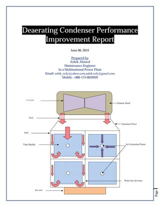
  • 1. Deaerating Condenser Performance Improvement Report June 06, 2012 Prepared by Ashik Ahmed Maintenance Engineer In a Multinational Power Plant Email: ashik_rofy@yahoo.com,ashik.rofy@gmail.com Mobile: +880-173-0059920 LP Cylinder Exhaust Hood Neck Transition Piece Shell Tube Bundle Air Extraction Points Page Hot well 1 Water box division
  • 2. THE STEAM TURBINE SPECIFICATION:REACTION REHEAT CONDENSING TYPE TWO CASING DOUBLE FLOW EXHAUST RATED OUTPUT 131,600 KW RATED SPEED 3,000 RPM MAIN STEAM PRESSURE 100 BAR A MAIN STEAM TEMPERATURE 565 ºC REHEAT STEAM PRESSURE 29.9 BAR A REHEAT STEAM TEMP. 565 ºC EXHAUST PRESSURE 0.060 BAR A MANUFACTURER: FUJI ELECTRIC PROBLEM:Absolute Pressure of Condenser Vacuum remains -697.24 (mmHg) but the value was -705 (mmHg) in few years back. So, the Steam turbine load can’t be operated to its maximum capacity. In the same time the water temperature Difference Between inlet & Outlet on Water Box-B Side shows ~2°c whereas temperature Diff. Between inlet & Outlet on Water Box-A Side shows ~5.4°c.The temperature difference should be quite near as they are handling the same condensate steam from Steam Turbine. POSSIBLE REASONS:Air Leakage Circulating water pumps (CWP) are not performing to its design capacity. Ejectors/vacuum pumps are not performing well Some extra steam load on condenser water box-A side cause the ∆T is extremely higher. Page 3 *** At first let we all try to understand what a Deaerating condenser. Some portions of next III pages are collected from a presentation of an unknown author (Probably a presentation of the former owner of this plant AES; during their commissioning time in Bangladesh).As it is very important for our understanding; I have included some portion (Literatures) of that presentation in to this report. ***
  • 3. WHAT ARE FUNCTIONS OF DEAERATING CONDENSER? Provide a heat sink within which to condense, and so recycle, the high quality feedwater allow increased heat/work transfer across the steam turbine by reducing the LP Turbine exhaust steam conditions Remove dissolved oxygen and non -condensable gases from the steam /condensate COMPONENTS OF THE CONDENSER The condenser is a single pressure, two pass, vertically divided water box design with its entire condensing surface (8,806 m2) in a single rectangular shell. Cooling Water, supplied from the Main Cooling Water System flows (CWP Maker:KSB) through the condenser tubes. Steam, expanded in the steam turbine, exhausts into the neck of the condenser through exhaust openings located after the final stages of the LP cylinder/Turbine. The steam then flows through the transition piece to the tube bundles located lower in the shell. Cooling water flows through the tube bundles. Steam cooled and condensed on the outside of the condenser tubes falls to the hot well located at the bottom of the condenser. The condensate is returned to the Steam/water cycle by the condensate extraction pumps (CEP Maker:KSB). The condensing steam reduces significantly in volume creating a reduced pressure in the condenser. The degree of negative pressure is dependent on the cooling water temperature which in turn affects the steam vapor pressure and temperature. Excess air is removed from the condenser steam space initially by the condenser vacuum pumps and any subsequent air and non condensable gases migrating into the condenser are removed by these pumps LP Cylinder Exhaust Hood Neck Transition Piece Shell Tube Bundle Air Extraction Points Hot well FIGURE 1 SIMPLIFIED DIAGRAM OF CONDENSER SHOWING TWO PASS Page 3 Water box division
  • 4. CONNECTIONS TO THE CONDENSER The following connections are made to the Condenser through the condenser flash box.              Cold Reheat Steam Dump Line HP Connection Pipe Drains MCV Downstream Drains ICV Upstream Drains HP/IP Outer Casing Drains HP/IP Inner Casing Drain HP/IP Balance Pipe Drain HP Front Gland Drain Turbine Gland Steam Header Drain LP Admission Steam Pipe Drain ACV Drain CRH Steam Check Valve Front Drain Flash Tank Drain It can be seen that all the turbine drains taken to the flash box are from a point downstream of the main HP, IP and LP Steam Isolating Valves. COOLING WATER CIRCUIT The cooling water circuit provides the heat exchange medium within the condenser. River Water is pumped through the condenser tubes by cooling water pump (CWP). Steam condenses on the outside of the tubes. The cooling water flow through the condenser produces a syphonic effect once the pipe work is fully charged with water; this in turn causes a negative pressure to appear at the outlet water boxes. The condenser cooling water outlet conduit is taken to a seal pit, which provides a fixed atmospheric breakpoint in the system. This ensures that during normal operation the pressure at the outlet water boxes, although negative, will remain above the vaporization pressure associated with the outlet temperature of the cooling water. Page 4 The Inlet, Return and Outlet Water boxes of the condenser are divided into two separate sections. Each section is served by independent inlet and outlet isolating valves. As a two pass circuit the water flows into the bottom or inlet water boxes, passes through a nest or bundle of tubes (lower quadrants) to the reversal or return water boxes, where it reverses direction and rises to the upper quadrants of the condenser before flowing through a second tube bundle to the outlet water boxes.
  • 5. Exhaust Steam from LP Turbine Upper Quadrants-Outlet Hot Water Send back to River after proper Heat Transfer Lower Quadrants-Inlet DEAERATING CONDENSER CWP -A CWP -B Relatively Cold water taken From River FIGURE 2 COOLING WATER CIRCUIT CONDENSER PERFORMANCE DEPENDS ON FOLLOWING PARAMETER MONITORING:During normal operation regular checks of the following parameters should be made and the values logged:      STG Load Air Leakage Inlet Cooling Water Temperature Outlet Cooling Water Temperature Absolute Pressure in Condenser ( Condenser Vacuum) The following values should be calculated and logged: Page The Cooling Water Temperature Rise is calculated from the difference between Cooling Water Outlet and Inlet Temperatures. The Initial Temperature Difference is calculated by first determining the steam saturation temperature for the current Condenser Pressure and the subtracting the Cooling Water Inlet Temperature. 5 The Cooling Water Temperature Rise Initial Temperature Difference Terminal Temperature Difference
  • 6. NOW WE WILL TRY TO FIND OUT THE POSSIBLE SOLUTION FOR CONDENSER VACUUM PROBLEM & SEVERE TEMPERATURE DIFFERENCE BETWEEN WATER BOX A & B. HISTORY OF CONDENSER  The Ejector erection was completed, commissioned and kept on operation on 14.08.04. 1st time both the ejector & vacuum pumps operation had started on 15.03.08.  Before that the condenser vacuum was maintained with either vacuum pump or ejector.  All vacuum pumps & ejector are in operation from 21.03.11 to till date.  The temperature difference between cooling water in/out on water box A & B had started from 07.10.11. CONDENSER DETAILS: DEAERATING CONDENSER Code: HEI (Ninth Edition) Heat Duty 799.1´106 KJ/h Empty Weight 165000 P.O. No. HAC-0004M-´-30466 Surface Area - 8806 m² Hot well Capacity- 35.3 m³ Operating Weight- 310 000 kg Mfg. Serial No.HE-00-026 Shell side Design Pressure 1.013 / F.V bar. A Design Temp.36.18 / 36.18 ºC Fluid: Steam Flow Rate : 357500 kg/h Hydro Test: Full of Water Tube side 3.5 / F.V bar. A 25 / 30.49 ºC River Water 34680000kg/h 5.25 Page  Extra loading to the condenser.(Valve passing)  Air ingression to the condenser.  Performance degradation of CWP pump.  Performance degradation of Ejector & vacuum pumps.  Temperature difference between condenser A & B side. i) Extra loading to the condenser.(Valve passing) Case:-I) The IP bypass stop valve HV-336B & PCV-336B has got huge passing. The IP bypass line PCV 336B was found passing on the last CI2012.Continuous condensate was found on that line. The line ends over the tubes of condenser A side. The condensate pressure was 4 bar that time, while on normal running condition the R/H outlet pressure is over 28 bar. The condenser inlet temperature (TE-336C) was found 196˚c on normal running condition. The temperature reduced to 150˚c while stopping the stop valve HV-336.But the stop valve also got passing that’s why the temperature didn’t come down. 6 Condenser Performance Degradation probable cause:
  • 7. Case:-II) HIP turbine drain valve 045A,045B.045D & 045 I was showing huge passing .The temperature on the downstream of this valves was observed (139.4°c ,245.3°c ,282.3°c & 504.2°c ).Whereas the other valves are having temp <45°c . This passing high temperature steams goes to the flash box, ultimately raising the temperature of the condenser water box. Case:-III) The drain valves of MOV-320c have got huge passing. The CEP discharge to the flash tank TCV-033E got 93% opening. Later on after closing the upstream isolation valve of MOV-320c,the TCV-033E Opening reduced to 43%. Case:-IV) The MOV-020(A, B, C &D) the HP SPR HTR & R/H outlet drain to the flash tank got some passing too. As the flash tank cep discharge TCV-033E opening also reduced a bit after closing the upper isolation valves. ii) Air Ingression to the Condenser The Crack over the IP Bypass line near spray water injection point could be checked again. The blind flange of condenser shell side shows loose bolts. All other line flange could be inspected through soap bubble test for finding air ingression. Page 7 III) Performance degradation of CWP pump.
  • 8. We can see from the technical data sheet that the flow will be increased on the increase of water level. CIRCULATING WATER PUMP:- CIRCULATING WATER PUMP MOTOR – Hyundai Made:- Hyundai 3 Phase induction motor, Model 1350VKNM Type: HLA7 902-36Y Serial No.KA0366-CWP-001 1100 KW, 12P, 6600 V 134.7 Amp Tag No. CW-M-PP-03-1 494 RPM, Efficiency : 94% Capacity 18,600 cu.m/hr. CosΦ :0.76 Total head 16m HPL overall, P.F, CosΦ =0.80 Design temp. 25 ºC Power (Bhp) 1100 Kw Speed 493 rpm CALCULATION:Date : 18.06.12 Given:CWP-A Current :- 109 A, Dish. Pr: 1.02Bar , Inside Water Level:- 7120 mm,Voltage: 6600 v Motor efficiency: 94% Assuming Pump efficiency on 85 % Assuming frictional loss =2 feet HPL overall, P.F, CosΦ =0.80 So, Motor Power = √3 x V x I x CosΦ =1.732 x 6600 x 114 x 0.80 = 104.25 KW So ,the Bhp = Motor Power x Efficiency of motor /0.746 =104.25 x 0.94/0.746 =1313.637 Hp The head of the pump,(feet)= pump discharge pressure (in abs) ± Suction head + friction loss H =(1.01325+1.09) x 14.7 x 2.31/specific gravity – (7.12-1.1) x 3.28+ 2 = 71.45 – 19.74+ 2 = 53.71 Feet We know Flow,Q= 3960 x ή x BHP H 3960 x 0.85 x 1313.637 53.71 = 82325.67 gal/min Or,we know Flow,Q= 550 x ή x BHP γH 550 x.85 x 1313.637 62.4 x 53.71 =183.238 feet3/sec = 18679.4 m3/hr =18698.19 m3/hr Page 8 The Cooling Water Pump flow is found up to the requirement; so can omit this from our cause list.
  • 9.  iv) Performance degradation of Ejector & vacuum pumps. We can see from the cooling water inlet temperature the vaccum will be 696 mmhg at cooling water inlet temp 32°c. Absolute pressure = atm pressure+ gauge pr. So, 0.085 bara= 1.01325 + gauge pr. Gauge pressure = 0.085 - 1.01325 = - 0.92825 bar = - 696mmHg We found the same vacuum on 16.06.10.So the ejectors & vacuum pumps are performing well.  v) Temperature difference between water box A & b Page **PLEASE SEE THE WATER BOX A & B INLET & OUTLET DATA ON NEXT PAGES FOR YOUR BETTER UNDERSTANDING.** 9 The condenser tube cleaning was done on CI-2012 & there was no significant variations on tubes were observed that time. So, either extra load is on A side or the circulating water is flowing less on water box A side. As the IP bypass line is just over the condenser water box A side, so there is a huge possibility of temperature increase.
  • 10. Several Data were taken on 5th & 6th Feb'12 on various discharge valve opening position due to Temperature Varience on Condeser Box A & B.. They are as follows:Condenser A Side Serial No Date Time Cooling Water Inlet Temp°C (A Side) TE-048A Cooling Water Outlet Temp°C (A Side) TE-048F Temp Differ °C (OutletInlet 5.8 5.6 5.7 5.3 5.5 5.8 7.1 6.9 7.2 1 2 3 4 5 6 7 8 9 10 12:44:11 12:48:43 12:49:00 05.02.12 14:24:28 14:28:26 14:30:20 5:26:27 6:26:03 06.02.12 7:25:40 13:42:32 22.2 22.2 22.2 22.3 22.3 22.3 22.2 22.2 22.2 22.5 28 27.8 27.9 27.6 27.8 28.1 29.3 29.1 29.4 28.5 11 15:04:24 22.6 29.1 Condenser B Side Pressure PT-048CA (Bar) Discharge Valve Opening % Cooling Water Inlet Temp°C (B Side) TE-048B Cooling Water Outlet Temp°C (B Side) TE-048G 25.1 25.2 25.3 26.6 26.3 26 27.3 27.9 26.7 58.2 58.2 58.2 58.3 58.3 40.6 6 0.72 0.78 0.79 0.76 0.71 0.77 0.71 0.79 0.8 0.71 62.7 62.8 43.4 62.4 22.4 22.4 22.5 22.6 22.7 22.6 22.4 22.3 22.4 22.7 6.5 0.91 37.5 22.9 Discharge Valve Opening % Seal Well Temp°C Vacuum mmHg (─) GTG Load MW STG Load MW Total Load MW 0.72 0.82 0.83 0.79 0.72 0.76 0.71 0.81 0.8 0.72 58.2 39.3 39.3 39.2 58.5 58.5 24.5 24.8 24.5 24.9 25.1 25 31.6 31.7 30.8 694.5 694.3 694.4 693.8 693.9 693.8 702.6 702.8 702.3 693.1 81.1 81.3 81.5 81 81.8 81 125.3 125.6 110.6 76.6 229.4 228.9 231.2 229.6 230.3 228.8 380.6 384.5 329.6 25.1 148.3 147.6 149.7 148.6 148.5 147.8 255.3 258.9 219 135.7 0.92 39.8 26.3 693.3 136.4 76.6 213 Temp Differ °C (OutletInlet) Pressure PT-048CB (Bar) 26.6 2.7 2.8 2.8 4 3.6 3.4 4.9 5.6 4.3 3.9 27.1 4.2 61.9 44.2 61.7 61.6 212.3 At 6th Feb 15:04 pm the vent line was open on both sides. The discharge valve was opened slowly & until water came out from the vent lines. Water didn't come from (048BA) discharge A side vent even on 37.5 % opening. As the CWP-A vibration was too high (Near 8.9 mm/s) ,the discharge valve didn't close more. Water came on rest of the valves:- I) Suction vent line of A side (048CA),II) Suction vent line of B side (048CB) & III) discharge vent line of B side (048DB). It is seen from the data that when the ST load is above (110~125 MW) or Total load is above (329~380MW) the seal well temperature became higher than the cooling water return temperatures (After the Condenser).Theoretically it is not possible until unless the following causes:● The thermocouples of return line (TE-048F & TE-048G) not functioning properly above 30°C OR ● Any underground pipe line near seal wall OR ● Any other operation causes. Remarks:The cooling water return temperature of Water box-A is higher than Water Box-B. As water is not coming even closing the water box-A discharge valve near 30% opening So, Top tubes of Condenser – A side is not getting water. ►As the cleaning will be carried out on Outage 2012, the answers could be found after inspecting the scale formation on the Water Box –A side top tubes. ►It could be assumed that the scale formation on Condenser water box-A is higher then the B side. ►As well as the opening of suction & discharge valves of the Condenser water box could be checked on the outage. ►Any steam leakage on A side where the The condenser inlet of IP bypass just above the tube bundles.
  • 11. Steam Turbine Condenser Vacuum Several Years Data on Several Steam turbine load & cooling water inlet & outlet temperature Water Water Box Water Box Box A Inlet Pr.A Outlet Pr.B Inlet Bar Bar Temp. °c Water Box A Outlet Temp °c . Date Ejector Vacuum Pump Ambient Temp Condenser Vacuum (mmHg) PT-032A 14.08.04 05.04.06 07.05.06 10.06.06 17.07.06 20.12.06 25.01.07 28.04.07(N) 01.08.07 16.12.07 16.01.08 24.02.08 14.03.08 In Service Isolated In Service In Service In Service In Service In Service In Service Isolated Isolated Isolated Isolated Isolated In Service Isolated Isolated Isolated Isolated Isolated Isolated In Service In Service (A, B & C) In Service (A& B) In Service (B) 27 23 26 31 20 16 27 28 20 20 21 28 -694.6 -690.1 -703.9 -698 -706.5 -721.8 -690.4 -699 -709 -696 -707 -705 231.5/53.0/350.5 245.1/46.6/361.3 248.1/45.5/308.3 237.8/50.3/375.3 249/55/337 257.4/52.1/340.1 226/55.7/384.5 247/46/359 241/31/328 233/42/325 252.8/53.6/355.1 227.6/41.4/316.2 15.03.08 In Service In Service (B) 28 -705 251.6/45.5/335.9 114 41.8 0.86 0.88 27.2 31.03.08 17.07.08 23.11.08 23 11 08 24.11.08 09.12.08 10.12.08 12.12.08 31.12.08 In Service In Service In Service In Service In Service In Service In Service In Service In Service (B) In Service (B) In Service (C) In Service (A & C) Isolated In Service (A, B & C) Isolated Isolated 28 31 21 21 21 21 22 18 -697 -702.8 -692 692 -687 -706 -692 -699.3 -709.2 262/48.9/326 251.3/46.9/317.4 247/54/343 230/43/318 198/50/277 214/68/359 257.3/39.3/321.4 240.5/43.8/350 122 123 125 108 93 105 118 120 43.8 41.9 43 44.2 38.1 43.2 40.6 38.3 0.78 0.83 0.69 0 69 0.5 0.68 0.69 0.74 0.66 0.79 0.85 0.7 07 0.51 0.69 0.69 0.74 0.67 30 29 27 27 27 26.9 27.1 23.5 36.3 35 33 35 30 29 32.2 28.5 19.04.09(D) In Service Isolated 30.8 -684.3 270.2/48.8/365.3 120 45.7 0.61 0.62 33.4 19.04.09(N) 20.04.09(D) 20.04.09(N) In Service In Service In Service In Service (A, B & C) In Service (A & C) In Service (A, B & C) 29.9 31.1 29 -685 -683.8 -685 233/43/313 224/48.2/354.7 233/43/313 106 122 116 45.2 45.9 45.2 0.54 0.58 0.54 0.58 0.59 0.58 18.01.10 In Service In Service (A) 13.4 -712.3 252/51/340 127 35.8 0.68 04.04.10 21.08.10 23.12.10 19.03.11 21.03.11 30.07.11 27.09.11 05.10.11 In Service In Service In Service In Service In Service In Service In Service In Service In Service (A & C) In Service (B) In Service (C) In Service (A & B) In Service (A, B & C) In Service (A, B & C) In Service (A, B & C) In Service (A, B & C) 29.3 29.7 17.2 27 27.3 30.4 21.9 26.6 -693.5 -692.1 -706 -700 -699.2 -695 -690 -685.6 267/47/352 260/52/364 242.0/53.4/321.0 247/49/138 271.3/52.0/337.7 246/49/340 245/53/371 245.2/48.6/319.4 260/49/54 242.8/46.8/53.8 122 124 117 119 122 119 123 112 42.7 42.9 38.1 40.5 40.7 43.6 44 44.7 07.10.11 In Service In Service (A, B & C) 31.5 -682.9 257.3/49.8/337.9 258.9/46.4/52.3 121 17.10.11 In Service In Service (A, B & C) 28 -676.5 222/42/306 224/42/49 19.10.11 In Service In Service (A, B & C) 27.8 -680.9 182/38/292 23.10.11 In Service In Service (A, B & C) 26.5 -689.1 25.12.11 In Service In Service (A, B & C) 13.1 -704.6 Water Box B Inlet Temp. °c Water Box B Outlet Temp. °c 33.6 HP/IP/LP Feed Water Flow (Ton/hr) HP/IP/LP Feed Steam Flow (Ton/hr) S/T Load MW Condenser Temp TE(033EA) °c Ejector erection completed, commissioned and kept on operation. All outage preparation done. 116 43.7 0.71 0.7 30.6 35.7 30.7 118 45.7 0.74 0.75 32.2 36.3 32.3 119 41.4 0.74 0.75 28.9 33.3 28.9 120 43.2 0.78 0.8 30.4 34.8 30.5 123 40.1 0.74 0.76 25.9 31.6 25.9 122 35.8 0.71 0.72 20.9 26.5 21.3 123 44.1 0.79 0.82 30.4 35.6 30.4 121 40.4 0.72 0.74 27.6 32.6 27.5 121 39.3 0.69 0.7 24.1 29 0 115 41.4 0.86 0.88 22.8 29.8 0 126 38.9 0.66 0.63 22.4 25 0 110 41.5 0.78 0.79 27.3 33.3 5.1 4.1 4.4 4.4 5.7 5.6 5.2 5 4.9 7 2.6 6 5 5.2 2.4 3.9 4.8 4.8 5 3.3 0 0 0 0 6.4 0 6.3 6 6 8 3 2.1 5.1 5 38.1 4.7 0 34 33.4 34 38 38.2 38 4 4.8 4 0 0 0 0.69 21.2 26.9 5.7 0 0.68 0.69 0.71 0.67 0.68 0.72 0.72 0.77 0.69 0.7 0.72 0.68 0.69 0.74 0.74 0.8 30.7 30.3 22.8 25.4 25.6 31.1 30 31.7 35.3 35.2 27.9 29.7 29.2 34.8 35.62 36.8 30.34 31.65 34.67 36 4.6 4.9 5.1 4.3 3.6 3.7 5.62 5.1 0 0 0 0 0 0 4.33 4.35 45.8 0.72 0.74 31.51 36.56 31.39 34 5.05 2.61 100 48 0.77 0.79 31.27 36.09 31.39 34.01 4.82 2.62 203/232/45 89 46 0.69 0.7 30.58 35.8 31.39 34.01 5.22 2.62 207/42/292 212/39/46 95 44 0.7 0.71 30.4 36.19 30.53 32.21 5.79 1.68 193/42/291 214/231/46 100 38.9 0.78 0.8 22.1 28.2 6.1 0 Remarks 0 6 0 0 0 0 0 0 29 35.7 37.5 31.3 34.4 30.7 26.1 35.4 30.8 0 0 0 Condens er IP By Diff. Betn Diff. Betn pass line inlet & inlet & Inlet Outlet on Outlet on Temp A Side B Side (TE°c °c 336C) °c 35 rom the 1st time both the ejector & vacuum pumps are in operation ST gland steam pressure is high probably due to the passing through pressure control valve. Ejector air valve and steam line has been closed due to vacuum fall in low load. The temperature difference between cooling water in/out on water box A & B has started the leakage steam were coming out from the upper side of welding joint crack and the joint is up of the Spray hose. Crack IP Bypass line near spray water injection point has been repaired by welding. IP by-pass PCV was opened to 10% to check vacuum and condenser temperature difference. But no vacuum was increased.
  • 12. Date Ejector Vacuum Pump Ambient Temp Condenser Vacuum (mmHg) PT-032A 22.02.12 19.03.12 In Service In Service In Service (A, B & C) In Service (A, B & C) 19.9 26.3 -698.5 -694.5 255/51/386 192/39/269 20.03.12 In Service In Service (A, B & C) 27.6 -685.6 21.03.12 In Service In Service (A, B & C) 25.9 27.03.12 25.04.12 11.05.12 05.06.12 10.03.12 10.06.12 11.06.12 In Service In Service In Service In Service In Service In Service In Service In Service In Service In Service In Service In Service In Service In Service (A, B & C) (A, B & C) (A, B & C) (A, B & C) (A, B & C) (A, B & C) (A, B & C) 12.06.12 In Service 12.06.12 12.06.12 12.06.12 Water Water Box Water Box Box A Inlet Pr.A Outlet Pr.B Inlet Bar Bar Temp. °c Water Box A Outlet Temp °c . Water Box B Inlet Temp. °c Water Box B Outlet Temp. °c 24.5 30 S/T Load MW Condenser Temp TE(033EA) °c 197/211/42 123 89 41.4 42.1 0.69 0.65 0.71 0.68 24.5 27.8 27 32.8 194/40/281 197/211/42 87 44.4 0.69 0.7 28 -685 203/42/256 204/38/45 91 44.2 0.68 0.72 28.7 31.9 31.8 24.1 30.3 32.4 33.1 -696.2 -689.6 -683.9 -685.4 -691.51 -693 -692.1 228/53/358 186.6/45.7/340.9 251.1/50.1/338.9 235.2/46.5/336.9 258/48/321 240/51/356 243.0/48.4/320.1 258/275/51 121 102 117 111 120 117 117 43.5 44.3 44.9 44.8 46.1 45.3 46.3 0.68 0.67 0.69 0.74 0.64 0.65 0.66 In Service (A, B & C) 33.19 -691.3 119.1 46 In Service In Service (A, B & C) 35.59 -698.9 119.6 In Service In Service (A, B & C) 36.9 -700.4 112 In Service In Service (A, B & C) 36.8 -701.2 117 14.06.12 In Service In Service (A, B & C) 32.41 -691.27 120.56 14.06.12 In Service In Service (A, B & C) 36.3 -688.044 116.36 14.06.12 In Service In Service (A, B & C) 36.16 -688.79 118.32 46.86 HP/IP/LP Feed Water Flow (Ton/hr) HP/IP/LP Feed Steam Flow (Ton/hr) 256/48/52 252.6/45.1/255 Condens er IP By Diff. Betn Diff. Betn pass line inlet & inlet & Inlet Outlet on Outlet on Temp A Side B Side (TE°c °c 336C) °c 2.5 5 5.5 0 32.1 4.1 0 28 32.6 4.6 0 0.72 0.7 0.71 0.76 0.66 0.68 0.685 29.3 31.3 31.6 31.4 32.7 31.6 32.9 35.4 36.6 37.2 37 38.1 36.8 38.1 6.1 5.3 5.6 5.6 5.4 5.2 5.2 0 0 0 0 0 0 0 0.63 0.66 32.5 37.9 32.8 34.8 5.4 2 194.56 45.7 0.65 0.68 32.2 37.6 32.4 34.6 5.4 2.2 191.36 45.5 0.62 0.65 32.3 37.6 32.5 34.3 5.3 1.8 187.12 46.1 0.65 0.67 32.7 38.1 32.8 34.8 5.4 2 186.16 45.92 32.65 38.09 32.79 34.7 5.44 1.91 192.2 46.36 33.09 38.59 33.44 35.28 5.5 1.84 188 33.25 38.63 33.38 35.38 5.38 2 45 Ejector HP/IP nozzle replacement work is going on. Ejector put back in service after HP & IP nozzles replacement. Vacuum was increased from 684.3 mmHg to -692.5 mmHg & ST load from 90 MW to 91.6 MW. 14.06.12 In Service In Service (A, B & C) 30.74 -689.38 119.5 46.89 33.54 38.77 33.81 35.81 5.23 2 196 16.06.12 In Service In Service (A, B & C) 26.51 -695 120.79 46 32.46 37.87 32.61 34.64 5.41 2.03 196 16.06.12 In Service In Service (A, B & C) 26.06 -697 121.51 45.63 31.75 37.21 31.84 34.12 5.46 2.28 192 16.06.12 In Service In Service (A, B & C) 26.52 -696.97 121.58 45.45 31.68 37.17 31.9 33.96 5.49 2.06 165 16.06.12 In Service In Service (A, B & C) 26.52 -696.97 121.58 45.45 31.68 37.17 31.9 33.96 5.49 2.06 160 16.06.12 In Service In Service (A, B & C) 25.66 16.06.12 In Service In Service (A, B & C) 26.52 12.06.12 -697.24 Service (A, B & C) Remarks 121.75 45.38 31.54 37.15 31.78 33.96 33.85 2.18 152 122.23 45.38 31.54 37.15 31.78 33.85 5.61 2.07 150.8 On IP by pass valve close & stop valve open position At 09:40 A.M On IP by pass valve close & stop valve close position At 12:07P.M On IP by pass valve close & stop valve close position At 13:59P.M On IP by pass valve close & stop valve close position At 15:26P.M On IP by pass valve close & stop valve open position At 09:00AM On IP by pass valve & stop valve close position At 14 PM On IP by pass PCV& stop valve close position as well as neck spray to the PCV for decrease of temp. on TE_336C At 16:00 PM On normal condition IP bypass PCV close & stop valve open condition . At: 22PM On IP by pass valve close & stop valve open position At 09:00AM On IP by pass valve & stop valve close position At 14 PM On IP by pass valve & stop valve close position At 15 PM On IP by pass valve & stop valve close position At 15 PM On IP by pass valve & stop valve close position At 16 PM On IP by pass valve & stop valve close position At 16:45PM The temperature on the IP bypass line(SB-001-FBD-750-P75 ) inlet on condenser (TE-336C) was showing 243.2 deg at 09:40 am in 12th June,2012.& the vacuum was -691.3 mmHg that time. The IP bypass line PCV 336B was found passing on the last CI-2012.Continuous condensate was found on that line. The line ends over the tubes of condenser A side. So the stop valve HV 336B was also stopped on 12th June 2012.The temperature decreased to 232.7 Deg & the vacuum found -701.2 mmHg on 15:26 pm on 12th June,2012. So the vacuum raise 10 mmHg due to the the reduction of probable passing on the PCV 336B. On 14th June,2012 the stop valve was again closed for vacuum improvement. But no significant rise of vacuum was observed. 14.06.12 The neck spray was manually operated that time & the condenser IP bypass line inlet temperature TE-336C was reduced from 200°c to 45 °c .The vent line of cooling water inlet was also vented. But no significant vacuum improvement was observed.
  • 13. Date Ejector Vacuum Pump Ambient Temp Condenser Vacuum (mmHg) PT-032A HP/IP/LP Feed Water Flow (Ton/hr) HP/IP/LP Feed Steam Flow (Ton/hr) S/T Load MW Condenser Temp TE(033EA) °c Water Water Box Water Box Box A Inlet Pr.A Outlet Pr.B Inlet Bar Bar Temp. °c Water Box A Outlet Temp °c . Water Box B Inlet Temp. °c Water Box B Outlet Temp. °c Condens er IP By Diff. Betn Diff. Betn pass line inlet & inlet & Inlet Outlet on Outlet on Temp A Side B Side (TE°c °c 336C) °c Remarks The upper isolation valve of HP super heater drain MOV 020A & B was manually closed. Some improvement on flash box was observed. Then the R/H outlet drain valve 320C's upstream isolation valve was manually colsed.The flash tank tank huge improvement was observerd.The cep discharge to flash tank TCV-033E was 92 % opened before the operation.After that the TCV was reduced to opening 44%. 16.06.12 then the PCV-336B & HV-336B was closed again .The condenser inlet of IP bypass (TE-336C) was 196°c then it had reduced to 153°c .The probable passing on IP bypass stop valve also. HIP turbine drain valve 045A,045B.045D & 045 I was showing huge passing .The temperature on the downstream of this valve was observed (139.4°c ,245.3°c ,282.3°c & 504.2°c ).Whereas the other valves are having temp <45°c . (*All of this operation was done with the help,suggesstion of Operation people *) 17.06.12 The IP bypass stop valve XV-336 & PCV-336B could be calibrated with the help of IC& E. The main stop valve is not closing properly as the condenser inlet temperature (TE-336C) is not reducing a lot. HIP turbine drain valve 045A,045B.045D & 045 got huge passing. The upstream isolation valves of MOV-320c,020A & B have got passing. The HP super heater drain line to condenser XV-045H might got passing. The blind flange of condenser shell side shows loose bolts. It should be tightened on convenient time eith proper scaffolding. All other line flange would be inspected through soap bubble test. The cooling water inlet vent lines to the condenser will be opened.
  • 14. CONCLUSION Probable Cause (I) :Air Leakage from condenser shell side. Answer:- We have to check all the flanges sealing condition by soap bubble test. Probable Cause (II) :Circulating water pumps (CWP) are not performing to its design capacity. Answer:- The current running data proves that the Cooling Water Pumps (CWP- A& B) are running still good though they are 12 years old. Probable Cause (III):Ejectors/vacuum pumps are not performing well. Answer:- The analysis shows the ejectors & vacuum pumps still are well enough for the operation. Probable Cause (IV):Some extra steam load on condenser water box-A side cause the ∆T is extremely higher. Answer:The IP bypass stop valve HV-336B & PCV-336B has got huge passing. The IP bypass line PCV 336B was found passing on the last CI-2012.Continuous condensate was found on that line. The line ends over the tubes of condenser A side. The condensate pressure was 4 bar that time, while on normal running condition the R/H outlet pressure is over 28 bar. HIP turbine drain valve 045A, 045B.045D & 045 got huge passing. The upstream isolation valves of MOV-320c, 020A & B have got passing. So, this is the probable cause of condenser under performance for the last few years. I hope the Steam turbine load can be reached to its maximum capacity after those valve maintenance works on the next Steam Turbine Major inspection on 2013.We hope we can increase our steam turbine load to 5-7 MW/D on that time. Thank You All Page I would also like to thank our operation team cause they have help us a lot also for problem finding. So, it’s a combined effort I believe & hope this report will be helpful for our Steam Turbine Capacity improvement after next MI-2013 & we can operate Steam Turbine like before. 14 This total report is a combined effort from our Haripur Power Limited (HPL) mechanical maintenance team. I want to thank our MMT Manager Mr. Zahid Hossain & MMT Supervisor Mr. AB Siddique for their continuous support.