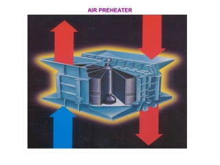
An air preheater is a heat exchanger that heats incoming combustion air by transferring heat from the flue gases before they are exhausted to the atmosphere. This improves boiler efficiency. There are two main types: recuperative, which uses stationary heat transfer surfaces, and regenerative, which uses rotating heat transfer surfaces. Proper operation and maintenance is important to minimize issues like air leakage, erosion, corrosion, plugging, and fouling that can reduce the air preheater's effectiveness over time. Regular inspection and cleaning helps maintain high performance.
The Presentation discusses the Air-Heater Performance Indices and the Boiler Performance calculation. One can Calculate the air ingress in the air-heater and the boiler and losses incurred thereby. The presentation also describes in details about the boiler efficiency and its calculation.
The presentation details about the Boiler Operation specifically while lightup of boiler and loading of boiler. the course participants discuss in details about the operations carried in their respective power stations
The presentation deals with the most complex and fundamental process in a CFBC boiler. i.e., Combustion. Provides an insight into the various features in a CFBC boilers which are incorporated to enhance cpmbustion.
Water steam Circuit in Supercritical Boiler for 660MW Power PlantHareesh VS
An animated presentation over Complete water steam circulation in a super critical boiler with flow chart. The water-steam path through various Systems (High pressure & Low pressure systems) in boiler for a 660MW thermal power plat, and also indicates the temperature and pressure variations after flowing through individual systems. Watch Live Presentation on YouTube: http://youtu.be/snIVrTmI4bM
The writeup details the Heat Balance of BHEL 210 MW Turbine Cycle. The Input and Output steam condition of Turbines, Extractions, Deaerator, LP Heaters, Condensers etc have been computed as per the specifications of the turbine manufacturer
Boiler purge is the basic process of resetting boiler before lightup. This presentation explains the logic, schematics & working of purge procedure. For enhanced knowledge of this topic, I can be reached at tahoorkhn03@gmail.com.
the presentation describes in details about the feed water and condensate heaters used in Thermal Power Stations or elsewhere. The performance parameters of the heaters are also described in details.
This PPT explains the logic and requirement behind Boiler Loss of Flame Protection under MFT. To know more about Boiler Loss of Flame please connect to tahoorkhn03@gmail.com
Heat/light/electrical energy is out today’s necessity and has scarcity also. Energy conservation is key requirement of any industry at all times.
In general, industries use heat energy for conservation of raw material to finished product. The source of heat energy is generally saturated or super heated steam. The steam generation is common use one boiler with carity of fuels. Whatever may be the fuel the generation should be as economy as possible which adds to the product cost. Further the usage of steam and recycling steam condensate back to boiler is an art depending on plant layouts.
In this project the steam generator is water tube boiler fired with rice husk. The steam is transferred to the tyre/tube moulds where tyres/tubes are cured while the heat is rejected to the tyres the condensate forms and this condensate is put back to the boiler. While doing so the steam is also stopped back to boiler without rejecting complete heat to the product. This gets flashed into atmosphere at feed water tank. The science of separation of condensate from steam saves energy. Better the separation more the fuel conservation.
In the steam generator the fuel is burnt to heat the water and form steam. This fuel burnt flue gas carries lot of energy, out through chimney. Prior to exhausting through the heat left in flue need to be recovered, through heat recovery mechanisms’. In this project an air-preheater condensate heat recovery unit is the major energy consuming station.
Afval heeft vaak nog energie potentieel. Bij de verbranding kan stoom opgewekt worden. Meer weten over de mogelijkheden van waste energy? Lees erover in deze presentatie inclusief een klanten case.
This was presented during the 9th annual refining summit 2015 in The Hague where key descision makers from the industry came together. One of the main topics was "How to increase energy efficiency & How to increase Profit marines" This presenation how the latent Bronswerk developments are supporting these targets.
3 show cases:
case 1: steam recompression
Case 2: debottlenecking ACHE with limited plotspace, limited available power and noise limitations
Case 3: debottlenecking ACHE with noise issues.
ABSTRACT
Heat/light/electrical energy is out today’s necessity and has scarcity also. Energy conservation is key requirement of any industry at all times.
In general, industries use heat energy for conservation of raw material to finished product. The source of heat energy is generally saturated or super heated steam. The steam generation is common use one boiler with carity of fuels. Whatever may be the fuel the generation should be as economy as possible which adds to the product cost. Further the usage of steam and recycling steam condensate back to boiler is an art depending on plant layouts.
In this project the steam generator is water tube boiler fired with rice husk. The steam is transferred to the tyre/tube moulds where tyres/tubes are cured while the heat is rejected to the tyres the condensate forms and this condensate is put back to the boiler. While doing so the steam is also stopped back to boiler without rejecting complete heat to the product. This gets flashed into atmosphere at feed water tank. The science of separation of condensate from steam saves energy. Better the separation more the fuel conservation.
In the steam generator the fuel is burnt to heat the water and form steam. This fuel burnt flue gas carries lot of energy, out through chimney. Prior to exhausting through the heat left in flue need to be recovered, through heat recovery mechanisms’. In this project an air-preheater condensate heat recovery unit is the major energy consuming station.
Condenser and Cooling Tower Power Plant EngineeringAjaypalsinh Barad
The file contains all details of the Condenser and Cooling Tower systems or Thermal power plant. This is the part of the subject Power Plant Engineering in GTU in 7th semester.
Process Heaters, Furnaces and Fired Heaters: Improving Efficiency and Reducin...Belilove Company-Engineers
A process heater is a direct-fired heat exchanger that uses the hot gases of combustion to raise the temperature of a feed owing through coils of tubes aligned throughout the heater. Depending on the use, these are also called furnaces or red heaters. Some heaters simply deliver the feed at a predetermined temperature to the next stage of the reaction process; others perform reactions on the feed while it travels through the tubes.
What is heat exchanger & its Functions
Types of Heat Exchangers
Compact Heat Exchangers
Part of Fin Plate Heat Exchangers
Advantages & Disadvantages of Fin Plate Exchangers
Materials & Manufacturing
Overall Heat transfer Coefficient & Fouling Factor
LMTD Method
Effectiveness - NTU Method
CFD Simulation of By-pass Flow in a HRSG module by R&R Consult.pptxR&R Consult
CFD analysis is incredibly effective at solving mysteries and improving the performance of complex systems!
Here's a great example: At a large natural gas-fired power plant, where they use waste heat to generate steam and energy, they were puzzled that their boiler wasn't producing as much steam as expected.
R&R and Tetra Engineering Group Inc. were asked to solve the issue with reduced steam production.
An inspection had shown that a significant amount of hot flue gas was bypassing the boiler tubes, where the heat was supposed to be transferred.
R&R Consult conducted a CFD analysis, which revealed that 6.3% of the flue gas was bypassing the boiler tubes without transferring heat. The analysis also showed that the flue gas was instead being directed along the sides of the boiler and between the modules that were supposed to capture the heat. This was the cause of the reduced performance.
Based on our results, Tetra Engineering installed covering plates to reduce the bypass flow. This improved the boiler's performance and increased electricity production.
It is always satisfying when we can help solve complex challenges like this. Do your systems also need a check-up or optimization? Give us a call!
Work done in cooperation with James Malloy and David Moelling from Tetra Engineering.
More examples of our work https://www.r-r-consult.dk/en/cases-en/
Industrial Training at Shahjalal Fertilizer Company Limited (SFCL)MdTanvirMahtab2
This presentation is about the working procedure of Shahjalal Fertilizer Company Limited (SFCL). A Govt. owned Company of Bangladesh Chemical Industries Corporation under Ministry of Industries.
TECHNICAL TRAINING MANUAL GENERAL FAMILIARIZATION COURSEDuvanRamosGarzon1
AIRCRAFT GENERAL
The Single Aisle is the most advanced family aircraft in service today, with fly-by-wire flight controls.
The A318, A319, A320 and A321 are twin-engine subsonic medium range aircraft.
The family offers a choice of engines
Water scarcity is the lack of fresh water resources to meet the standard water demand. There are two type of water scarcity. One is physical. The other is economic water scarcity.
Welcome to WIPAC Monthly the magazine brought to you by the LinkedIn Group Water Industry Process Automation & Control.
In this month's edition, along with this month's industry news to celebrate the 13 years since the group was created we have articles including
A case study of the used of Advanced Process Control at the Wastewater Treatment works at Lleida in Spain
A look back on an article on smart wastewater networks in order to see how the industry has measured up in the interim around the adoption of Digital Transformation in the Water Industry.
Explore the innovative world of trenchless pipe repair with our comprehensive guide, "The Benefits and Techniques of Trenchless Pipe Repair." This document delves into the modern methods of repairing underground pipes without the need for extensive excavation, highlighting the numerous advantages and the latest techniques used in the industry.
Learn about the cost savings, reduced environmental impact, and minimal disruption associated with trenchless technology. Discover detailed explanations of popular techniques such as pipe bursting, cured-in-place pipe (CIPP) lining, and directional drilling. Understand how these methods can be applied to various types of infrastructure, from residential plumbing to large-scale municipal systems.
Ideal for homeowners, contractors, engineers, and anyone interested in modern plumbing solutions, this guide provides valuable insights into why trenchless pipe repair is becoming the preferred choice for pipe rehabilitation. Stay informed about the latest advancements and best practices in the field.
Vaccine management system project report documentation..pdfKamal Acharya
The Division of Vaccine and Immunization is facing increasing difficulty monitoring vaccines and other commodities distribution once they have been distributed from the national stores. With the introduction of new vaccines, more challenges have been anticipated with this additions posing serious threat to the already over strained vaccine supply chain system in Kenya.
NO1 Uk best vashikaran specialist in delhi vashikaran baba near me online vas...Amil Baba Dawood bangali
Contact with Dawood Bhai Just call on +92322-6382012 and we'll help you. We'll solve all your problems within 12 to 24 hours and with 101% guarantee and with astrology systematic. If you want to take any personal or professional advice then also you can call us on +92322-6382012 , ONLINE LOVE PROBLEM & Other all types of Daily Life Problem's.Then CALL or WHATSAPP us on +92322-6382012 and Get all these problems solutions here by Amil Baba DAWOOD BANGALI
#vashikaranspecialist #astrologer #palmistry #amliyaat #taweez #manpasandshadi #horoscope #spiritual #lovelife #lovespell #marriagespell#aamilbabainpakistan #amilbabainkarachi #powerfullblackmagicspell #kalajadumantarspecialist #realamilbaba #AmilbabainPakistan #astrologerincanada #astrologerindubai #lovespellsmaster #kalajaduspecialist #lovespellsthatwork #aamilbabainlahore#blackmagicformarriage #aamilbaba #kalajadu #kalailam #taweez #wazifaexpert #jadumantar #vashikaranspecialist #astrologer #palmistry #amliyaat #taweez #manpasandshadi #horoscope #spiritual #lovelife #lovespell #marriagespell#aamilbabainpakistan #amilbabainkarachi #powerfullblackmagicspell #kalajadumantarspecialist #realamilbaba #AmilbabainPakistan #astrologerincanada #astrologerindubai #lovespellsmaster #kalajaduspecialist #lovespellsthatwork #aamilbabainlahore #blackmagicforlove #blackmagicformarriage #aamilbaba #kalajadu #kalailam #taweez #wazifaexpert #jadumantar #vashikaranspecialist #astrologer #palmistry #amliyaat #taweez #manpasandshadi #horoscope #spiritual #lovelife #lovespell #marriagespell#aamilbabainpakistan #amilbabainkarachi #powerfullblackmagicspell #kalajadumantarspecialist #realamilbaba #AmilbabainPakistan #astrologerincanada #astrologerindubai #lovespellsmaster #kalajaduspecialist #lovespellsthatwork #aamilbabainlahore #Amilbabainuk #amilbabainspain #amilbabaindubai #Amilbabainnorway #amilbabainkrachi #amilbabainlahore #amilbabaingujranwalan #amilbabainislamabad
Sachpazis:Terzaghi Bearing Capacity Estimation in simple terms with Calculati...Dr.Costas Sachpazis
Terzaghi's soil bearing capacity theory, developed by Karl Terzaghi, is a fundamental principle in geotechnical engineering used to determine the bearing capacity of shallow foundations. This theory provides a method to calculate the ultimate bearing capacity of soil, which is the maximum load per unit area that the soil can support without undergoing shear failure. The Calculation HTML Code included.
Hybrid optimization of pumped hydro system and solar- Engr. Abdul-Azeez.pdffxintegritypublishin
Advancements in technology unveil a myriad of electrical and electronic breakthroughs geared towards efficiently harnessing limited resources to meet human energy demands. The optimization of hybrid solar PV panels and pumped hydro energy supply systems plays a pivotal role in utilizing natural resources effectively. This initiative not only benefits humanity but also fosters environmental sustainability. The study investigated the design optimization of these hybrid systems, focusing on understanding solar radiation patterns, identifying geographical influences on solar radiation, formulating a mathematical model for system optimization, and determining the optimal configuration of PV panels and pumped hydro storage. Through a comparative analysis approach and eight weeks of data collection, the study addressed key research questions related to solar radiation patterns and optimal system design. The findings highlighted regions with heightened solar radiation levels, showcasing substantial potential for power generation and emphasizing the system's efficiency. Optimizing system design significantly boosted power generation, promoted renewable energy utilization, and enhanced energy storage capacity. The study underscored the benefits of optimizing hybrid solar PV panels and pumped hydro energy supply systems for sustainable energy usage. Optimizing the design of solar PV panels and pumped hydro energy supply systems as examined across diverse climatic conditions in a developing country, not only enhances power generation but also improves the integration of renewable energy sources and boosts energy storage capacities, particularly beneficial for less economically prosperous regions. Additionally, the study provides valuable insights for advancing energy research in economically viable areas. Recommendations included conducting site-specific assessments, utilizing advanced modeling tools, implementing regular maintenance protocols, and enhancing communication among system components.
2. INTRODUCTION:
HEAT EXCHANGER
HEAT TRANSFER FROM FLUE GAS TO AIR
HEAT REJECTED TO ATMOSPHERE REDUCED
INCREASE BOILER EFFICIENCY BY STABILITY OF COMBUSTION
WITH HELP OF HOT AIR.
HOT AIR USED FOR DRYING THE COAL AS WELL AS FOR
TRANSPORTING.
FOR EVERY 20°C DROP IN FLUE GAS EXIT TEMPERATURE THE
BOILER EFFICIENCY INCREASE BY ABOUT 1%.
10% IMPROVEMENT IN BOILER EFFICIENCY WHEN
COMPARED TO AN IDENTICAL UNIT WITHOUT AN APH.
3. Why APH in Boiler System
• APH - Tail ender
• APH & Economizer are heat recovery
• surface
• Designers always look at this in pair
• Economizer - self limiting characteristics
• Can steam if not properly sized
• Minimum 25 – 30 deg C Eco out F W
& saturation temperature
• APH can be sized for any requirement
• APH has ability to absorb changes
4. TYPES OF AIR PREHEATERS:
AIR PREHEATERS CAN BE CLASSIFIED AS RECUPERATIVE AND
REGENERATIVE TYPES BASED ON THEIR OPERATING PRINCIPLE.
IN RECUPERATIVE TYPE HEATING MEDIUM I.E. FLUE GAS IS ON ONE
SIDE AND AIR IS ON THE OTHER SIDE OF TUBE OR PLATE AND THE
HEAT TRANSFER IS BY CONDUCTION THROUGH THE MATERIAL
WHICH SEPARATES THE MEDIA. THESE ARE OF STATIC
CONSTRUCTION AND HENCE THERE IS ONLY NOMINAL LEAKAGE
THROUGH EXPANSION.
IN REGENERATIVE TYPE THE HEATING MEDIUM FLOWS THROUGH A
CLOSELY PACKED MATRIX TO RAISE ITS TEMPERATURE AND THEN
AIR IS PASSED THROUGH THE MATRIX TO PICK-UP THE HEAT.
EITHER THE MATRIX OR THE HOODS ARE ROTATED TO ACHIEVE
THIS AND HENCE THERE IS SLIGHT LEAKAGE THROUGH SEALING
ARRANGEMENTS AT THE MOVING SURFACES.
5. TYPES
RECUPERATIVE RE-GENERATIVE
STATIC CONSTRUCTION ROTARY BY CONSTRUCTION
TUBULAR TYPE
PLATE TYPE
SCAPH
TRI-SECTOR
BI-SECTOR
Quad-Sector
ROTHEMUHLE
MATRIX ELEMENT STATIONARY
LJUNGSTROM TYPE
MATRIX ELEMENT ROTATING
HEAT PIPE or THERMOSYPHONE
6. TUBULAR AIR PREHEATER (RECUPERATIVE):
•LARGE NUMBER OF STEEL TUBES OF 40 TO 65 MM DIA.
•EITHER WELDED OR EXPANDED INTO THE TUBE PLATES.
•EITHER GAS OR AIR FLOW THROUGH THE TUBE.
•GAS THROUGH THE TUBE NORMALLY REQUIRES HIGHER SIZE TUBE
AND VERTICAL FLOW TO REDUCE FOULING.
•SINGLE OR MORE PASSES ON THE GAS SIDE AND MULTIPASS CROSS
FLOW ON THE AIR SIDE USUALLY FITS IN WITH THE OVERALL PLANT
DESIGN.
•THE PORTION OF AIRHEATER AT LOW TEMPERATURE ZONE IS
DESIGNED NORMALLY WITH A SHORTER TUBE LENGTH SO AS TO
FACILITATE MAINTENANCE OF SURFACES DUE TO CORROSION AND
FOULING.
PLATE TYPE AIR PREHEATER (RECUPERATIVE):
•THESE COMPRISE OF PARALLEL PLATES.
• WHICH PROVIDE ALTERNATE PASSAGE FOR GAS AND AIR.
•THIS TYPE IS SIMPLE AND COMPACT COMPARED TO THAT OF TUBULAR
TYPE.
•THE NARROW PASSES BETWEEN PLATES MAKE THE CLEANING
TEDIOUS BUT WITH SHOT CLEANING METHOD IT IS IMPROVED.
•REPLACEMENT IS A MAJOR TASK.
7.
8.
9. LJUNGSTROM REGENERATIVE AIR - HEATER
•THE HEAT TRANSFER ELEMENTS ARE ROTATED AT A CONSTANT
SPEED AND THEY PASS ALTERNATELY THROUGH GAS AND AIR
PASSES.
•THE AXIS OF ROTATION MAY BE HORIZONTAL OR VERTICAL.
•THE DRIVE IS NORMALLY ELECTRICAL OPERATED THROUGH
REDUCTION GEAR WITH COMPRESSED AIR MOTOR AS STAND-BY.
•THE PLATES FORMING THE ELEMENTS (MATRIX) MAY BE VARIED IN
SPACING AND THICKNESS.
•COLD ENDS ARE MADE OF SPECIAL CORROSION RESISTANCE ALLOY
SUCH AS CORTEN OR ENAMELED TO ACHIEVE CORROSION
RESISTANCE.
•THIS TYPE IS VERY COMPACT AND LENDS EASILY FOR DUCTING
ARRANGEMENT EFFECTIVE CLEANING OF HEAT-TRANSFER SURFACE
BY SOOT BLOWING IS POSSIBLE.
10. • THE BASIC COMPONENT OF THE CONTINUOUSLY ROTATING
CYLINDER, CALLED THE ROTOR, THAT IS PACKED WITH THOUSANDS OF
SQUARE FEET OF SPECIALLY FORMED SHEETS OF HEAT TRANSFER
SURFACES.
• AS THE ROTOR REVOLVES, WASTE HEAT IS ABSORBED FROM THE
HOT EXHAUST GAS PASSING THROUGH ONE HALF OF THE SURFACE.
• THIS ACCUMULATED HEAT IS RELEASED TO THE INCOMING AIR AS
THE SAME SURFACES PASS THROUGH THE OTHER HALF OF THE
STRUCTURE. THE HEAT TRANSFER CYCLE IS CONTINUOUS AS THE
SURFACES ARE ALTERNATELY EXPOS ED TO THE OUTGOING GAS AND
INCOMING AIR STREAMS.
• FUEL SAVINGS WITH THE LJUNGSTRÖM AIR PREHEATER ARE
ABOUT 1-1½% FOR EVERY 4.4°C TO 10°C INCREASE IN COMBUSTION
AIR TEMPERATURE, DEPENDING ON THE APPLICATION.
•THEIR SIMPLIFIED DESIGN AND OPERATING INTEGRITY ASSURE
CONTINUOUS RELIABLE SERVICE THROUGHOUT THE LIFE OF THE
PLANT.
11. Size Type Rotor Dia (Meters) Heat Duty(M.K.Cals/Hr)
7 - 16.5 K 1.2 - 3.0 2.5 - 60
17 - 18.5 S 3.2 - 3.8 50 - 70
19 - 24 R 4.2 - 6.6 70 - 200
24.5 - 36 LARGE 6.9 - 20.0 > 200
Range of RAPH
Designation of RAPH
27 VI M T 2000
Size number
Vertical Shaft; Inverted gas Flow
Modular Rotor
Trisector
Element depth in
mm
13. BI-SECTOR
THE MAJORITY OF LJUNGSTRÖM
AIR PREHEATERS SUPPLIED ARE IN
THE BI- SECTOR DESIGN. THESE
HEATERS HAVE TWO BASIC
STREAMS, ONE OF GAS AND ONE OF
AIR.
14. TRI-SECTOR
TRI-SECTOR AIR PREHEATER PERMITS A SINGLE HEAT EXCHANGER
TO PERFORM TWO FUNCTIONS: COAL DRYING AND COMBUSTION AIR
HEATING.
THE DESIGN HAS THREE SECTORS - ONE
FOR THE FLUE GAS, ONE FOR THE PRIMARY
AIR THAT DRIES THE COAL IN THE
PULVERIZER, AND ONE FOR SECONDARY
AIR THAT GOES TO THE BOILER FOR
COMBUSTION
15. • QUADSECTOR
•THE QUAD-SECTOR IS WITH FOUR
FLOW STREAMS THROUGH THE
ROTOR.
•THE FOUR SECTORS COMPROMISE ONE GAS AND
ONE PRIMARY AIR AS IN THE TRI- SECTOR, BUT
THERE ARE TWO SEPARATE SECONDARY AIR
SECTORS.
•THE DESIGN HAS THE PRIMARY AIR SECTOR’ FLANKED' ON EITHER
SIDE BY SECONDARY AIR, AND THIS HAS A BENEFIT ON THE TOTAL AIR-
TO-GAS LEAKAGE OF THE UNIT.
16. AIR HEATER –(SCHEMATIC)
RADIAL SEAL
AXIAL
SEAL
BYPASS SEAL
COLD END
HOT END
HOT INTERMEDIATE
GUIDE BEARING
SUPPORT BEARING
17.
18. ROTOR:
The rotor is the heart of the equipment radially divided open ended cylinder which
contains the heating surface elements. The center shaft of the rotor is called the
post. Diaphragm plates extend out ward from the post dividing the rotor into 12 or 24
sectors which are further divided to form compartments into which the element
baskets are packed-A pin rack is located around the outside of the rotor to allow it to
be rotated by the drive mechanism.
19.
20. HEATING ELEMENTS:
They are packed in a reversible containers called baskets, are placed in
rotor in three tiers: - Hot, Intermediate and Cold.
The notches are used for maintaining the spaces between the elements
and minimizing the pressure drop across the air preheater.
21. • HOT END BASKETS & HOT INTERMEDIATE : -
Hot End is the first layer & Hot Intermediate is second layer of heating element
packing from hot end side. The elements are usually made from 24 gauge / 22
gauge(0.5 – 0.8MM) open hearth steel (IS 513 Gr. DD). They are having a
profile called “Double Undulation. The notches run parallel with the rotor axis
and provide the correct spacing of sheets and the undulations run at 60° to the
notches to impart turbulence. Open-channel element, where the notches, which
provide the required plate spacing, rest on a series of point contacts on the
adjacent sheet. Flow can move across the element pair because there are
openings between the two sheets along the flow length between point contacts.
22. COLD END BASKETS
The elements are made of 18 gauge / 22 gauge carton steel. Enameled elements
are also used in severe corrosive conditions like for more percentage of sulphur in
fuel or for low gas duct temperature. All the heating surface elements are packed
into reversible containers called baskets to facilitate easy removal and handling.
Cold end baskets are arranged for removal through the basket removal door in the
housing.
A closed element profile is the notched flat 6-mm element (NF6), the element pair
is formed by a series of notches that rest on an adjacent flat sheet with contact
along the total flow length. They provide the necessary spacing and form discrete
individual flow channels of fixed cross-sectional area along the flow length or
element depth. There is no flow communication from one channel to the adjacent
one.
23. AIR LEAKAGE
• Leakage of the higher pressure air to the lower pressure flue gas
through the clearances between the rotor seals and the sector plates.
• Air to gas leakage can be increase with time, to more than twice the
immediate post overhaul level.
• Can be increase with increase in differential pressure of
two fluids
• Leakage paths for a tri-sector APH are more complex, compared
to a bi-sector .
• In a tri-sector , primary air leaks into the flue gas and secondary
air streams, while SA leaks into the flue gas stream.
• Leakage occurs both on the cold end (CE) and hot end (HE).
• Due to large difference in pressure between the PA and SA
streams, as well as the PA and flue gas streams, leakage in a
tri-sector APH is higher than in a bi-sector APH.
• Air leakage has the largest single effect on APH performance.
• Two penalties to boiler performance occur with excessive radial seal leakage.
1.Thermal losses associated with the leakage air cooling the APH.
2. Additional auxiliary horsepower consumed by the fans for pushing more flow.
24. TYPE OF AIR LEAKAGE
A. ENTRAINED LEAKAGE :
B. DIRECT LEAKAGE :
• THIS IS MAINLY ENTRAPED AIR IN BETWEEN THE HEATING ELEMENTS
We = γ . v . rpm. 60
γ = Sp. Wt of air in Kg/m3
v = Volume of Rotor air space
• THIS IS MAINLY DUE TO DIFFERENTIAL PRESURE OF TWO FLUID
• INCREASE OF SEAL CLEARANCE AT HOT CONDITION
• EROSION OF SEALS
• IMPROPER SEAL SETTING
Wd = α ∗ A *√(2g * γ * ∆ P)
α= Coeff. Of flow rate (0.6 – 0.7)
g= Acceleration due to gravity
A= Gap area at hot condition (m2
)
∆P= Diff. pr. Of two fluids
γ = Sp. Wt of air in Kg/m3
Variable factors are Α & ∆P
* Hence amount of entrained Leakage is independent of operating and maintenance condition
25. Circumferential
bypass seal leakage
into the warm airflow
Peripheral bypass
seal leakage into the
gas path
Circumferential
bypass seal
leakage into the
cold gas flow.
Hot radial
seal leakage
Cold radial
seal leakage
VARIOUS LEAKAGE PATHS THROUGH THE APH
26. It is noted that nearly
80-85% leakage is
from Radial Seal
10-15% through By-
Pass Seal
5-10% through Axial
LEAKAGE PATH
27. THERMAL TURNDOWN
When the APH rotor is heated from a
cold condition (blue), thermal
expansion (yellow) can cause the rotor
to droop or “turn down” up to 3 inches
on the periphery. Knowing the amount
of turndown is important when
presetting the seal position before
operation, because seal positions will
change as the rotor warms to its
operating temperature.
28. • SEALING SYSTEM COMPRISES THE
FOLLOWING:
– RADIAL SECTOR & AXIAL SEALING PLATE
– RADIAL, CIRCUMFRENCIAL & AXIAL SEALS
– ROTOR POST SEALS
– INBOARD & OUTBOARD STATIC SEALS
SEALING SYSTEM
29. SEALING SYSTEM: -
Usually air leaks into the gas stream due to static pressure differential. This leakage
air decrease the air leaving temperature. Various arrangements to reduce the
leakage are as follows.
The sealing arrangement consists of Radial, Axial, Bypass, Axial Seal Plate to
Sector Plate, Static, Rotor Post Seals and Mechanical Sealing Plates designed to
minimize leakage between the gas and air streams of the pre-heater.
THE RADIAL SEALS are located along the edges of the diaphragm plates and bear
against the sector plates, housed under centre sections.
THE AXIAL SEALS are located axially in line with the outer edge of diaphragm
plates and bear against the axial seal plates, mounted in the housing pedestals.
THE BYPASS SEALS are located on the housing around the periphery of the rotor
and bear against the T-bar attached to the periphery of the rotor.
THE AXIAL PLATE TO SECTOR PLATE SEALS are attached to the axial seal plats
and bear against the sector plates.
THE STATIC SEALS are fixed under the centre sections and housing pedestals and
bear against sector plates and axial seal plates respectively.
THE ROTOR POST SEALS are attached to the ends of the rotor posts and bears
against the sector plates.
30. SEALING SYSTEM: -
– SINGLE LEAF TYPE
• Only one sealing strip passing under sector plate & axial seal plate
any one time.
• Adjusted with no gap due to sharp edge & bend.
• 6% reduction in radial seal leakage than channel type.
33. Gaps are observed around the Baskets and with Diaphragm/Stay
plates. This will by-pass the flue gas: thereby loosing the efficiency of
the boiler. This is revealed by the high flue gas outlet temperature.
The newly developed erosion resistant ‘Basket Bypass Seal’, which will
permanently close the gaps till the next replacement of the baskets.
This will result in lower flue gas outlet temperature, which will improve
the efficiency of the Boiler.
BASKET BYPASS SEAL
34. CIRCUMFERENTIAL SEALS DEFLECTORS
Ideas for deflector Plates and Clay Cloth seals which cater
for thermal load dependant rotor position fluctuations have
been devised previously.
35. EROSION
Erosion caused by fly ash has resulted in the rapid loss of a heat exchange
element as well as damage to perimeter seals, radial seals, and rotor
diaphragms. Two other factors with regard to erosion are actually more
important than ash content: abrasiveness and ash velocity.
The abrasiveness of fly ash increases as the amount of silica and alumina
increases.
Ash velocity is as much as three times more important than ash content or
abrasiveness when it comes to determining the rate of erosion. One way to defeat
high ash velocity is to increase the fineness of the coal particles leaving the
pulverizers and balancing the coal and air flows to each of the burners.
36. CORROSION, PLUGGING AND FOULING
A lower flow rate of combustion air results in a lower furnace excess air
(excess O2) level, increased CO emissions, increased levels of unburned
fuel in fly ash, higher furnace exit gas temperature, increased slagging
and fouling rates, and higher net unit heat rate.
Cold End Heating elements were seriously affected by corrosion
mainly in oil fired boilers. Corrosion causes due to formation of
sulphuric acid.
To avoid corrosion:
a. Complete combustion of fuel oil to be ensured.
b. Soot blowing at regular intervals to be done.
c. Maintaining minimum cold end average temperature.
d. Heating elements to be dried properly after water washing.
e. Oil quality to be ensured.
37. FOULING, PLUGGING AND CORROSION:
? Deposits are initiated by condensation of acid or moisture from flue gas on
metal surface operating at temperature below dew point i.e. mainly at the cold
end, where, as a result, most fouling and corrosion occur.
? Degree of fouling depends on heating element metal surface.
? As coal contains less sulphur, corrosion is not normally as much a problem
as fouling and hence lower exit gas temperature to a level of 120 C is
permissible.
? But in the case of oil firing, the corrosion and plugging due to corrosive
products of combustion are very common.
? The gas outlet temperature and/or air inlet temperature has to be raised to
restrict the corrosion to the permissible level.
? Operating the oil fired boiler at very low excess air reduces the acid formation
and hence corrosion.
? During starting and at low loads the flue gas exit temperature falls to a low
value that will lead to corrosion.
38. One or some of the following method is used to combat the problem:
1. Use of low sulphur oil during the above condition.
2. Air inlet temperature is increased mostly by steam air heating to maintain the
recommended cold end average temperature for the installation.
2. Corrosion resistant alloys like corten steel can be used for cold end.
3. Easily and economically replaceable cold end portion of airheater without much
outage period.
4. Effective on-load blowing of airheaters with superheated steam as moisture in
steam accelerates fouling and corrosion.
39. APH THERMAL EFFICENCY
• Gas side efficiency ‘η’gas.
• Air side efficiency ‘η’air.
• X-Ratio.
IF: -
Tgi = APH Gas inlet temperature.
Tgo = APH Gas outlet temperature.
Tai = APH air inlet temperature.
Tao = APH air outlet temperature
Tgo (nl) = APH Gas outlet temperature at no seal leakage.
40. APH GAS SIDE EFFICIENCY
Flue gas inlet temp. – Flue gas outlet temp. at no seal leakage
=
Flue gas inlet temp. – Air inlet temp.
Tgi – Tgo (nl)
=
Tgi – Tai
TgO (nl) = Corrected gas temp. for no seal leakage
Al X Cpa (Tgo – Tai)
= + Tgo
100 X Cpg
AL = % Seal leakage on wt.
O2 out – O2 in
= X 100 X (0.9 for coal)
21 – O2 o
Cpa = Mean specific Heat between Tgi and Tgo
Cpg = Mean specific Heat between Tgo and Tgonl
Cpa / Cpg = 0.95 for Coal
41. Tao - Tai
ηai = X 100%
Tgi - Tai
Tgi – Tgo (nl) ηgas
X-Ratio = =
Tgi – Tai ηair
20°C rise in flue gas exist temperature there is decrease in boiler η 1% i.e. =
loss of 26 Kcal approx.
42. DRIVE ARRANGEMENT : -
The drive mechanism consists of:
• Two electric motor connected to a gear reduction unit through
overrunning clutch and fluid coupling driving a pinion gear.
• The pinion gear meshes with a pin rack on the rotor which allows the
rotor to rotate at a low speed.
• Provision of Air Motor is also given for any failure of electric drive units.
Rotor Drive Assembly (Down Shaft Design)
1. High Speed Coupling
2. Drive Motor (Main)
3. Pin Rack
4. Rotor Housing.
5. Support Bracket
6. Pinion
7. Pinion Cover
8. Speed Reducer
9. Air Motor (Auxiliary)
43. 07. Motor – TEFC: 11 KW, 3
Phase,
50 Hz, 415 V,
1450 RPM,
05-06 Speed Reducer : Type – I
Japan,
Rissowai
09. Coupling : 11.50 FCU
(Pembril)
08. Air Motor = Chiago Pneumatic
Air
Motor RSM 400
10. Coupling = Bibby 124 A