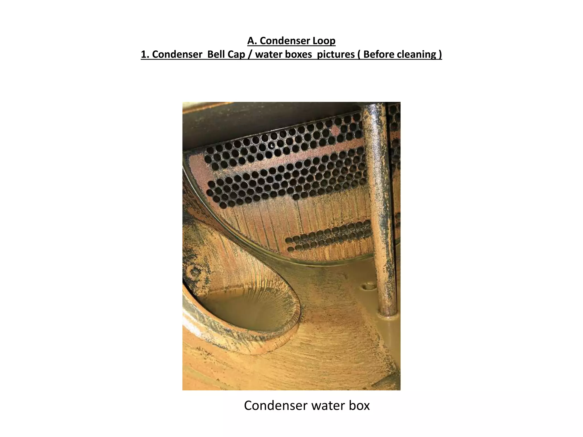
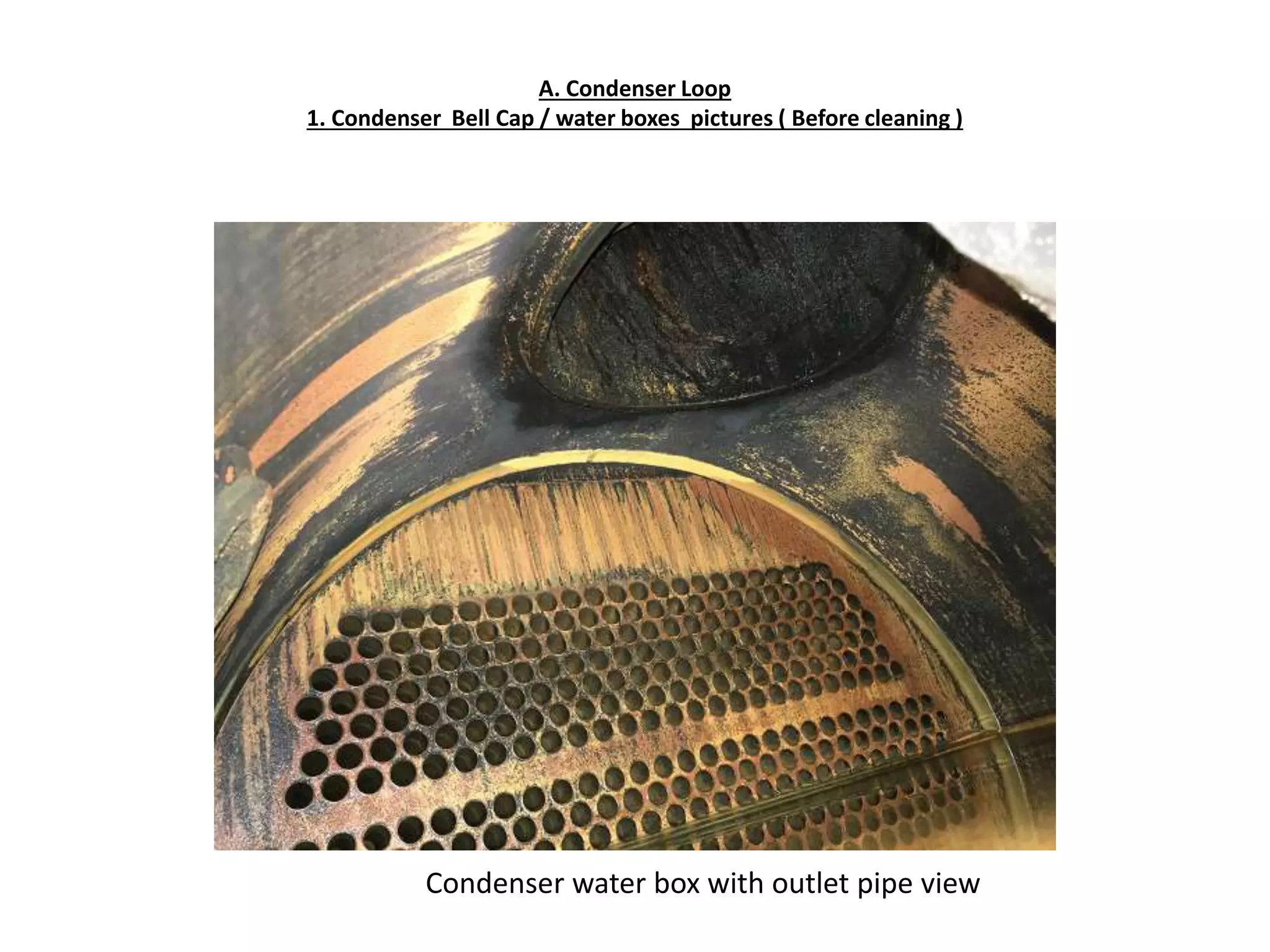
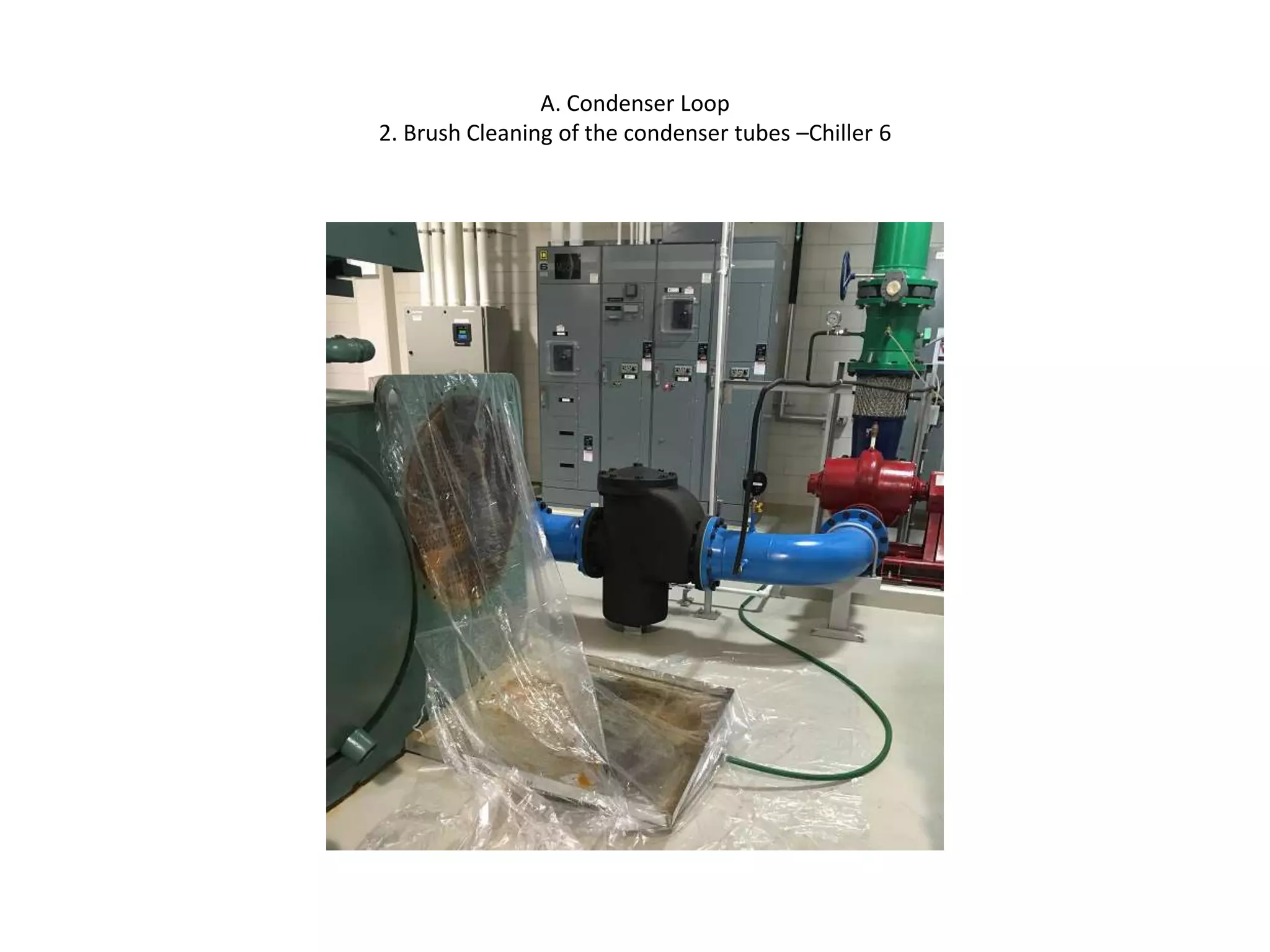
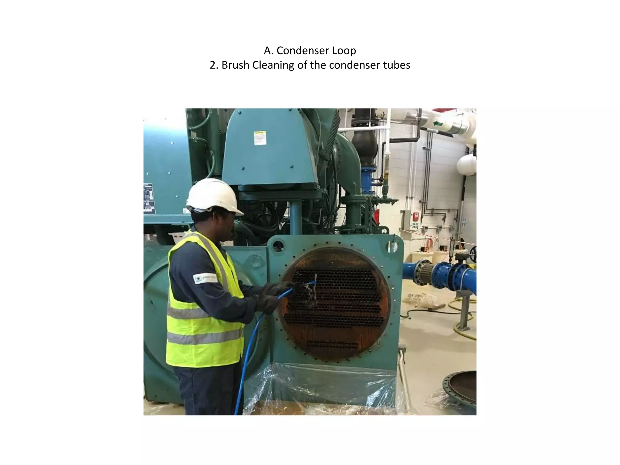
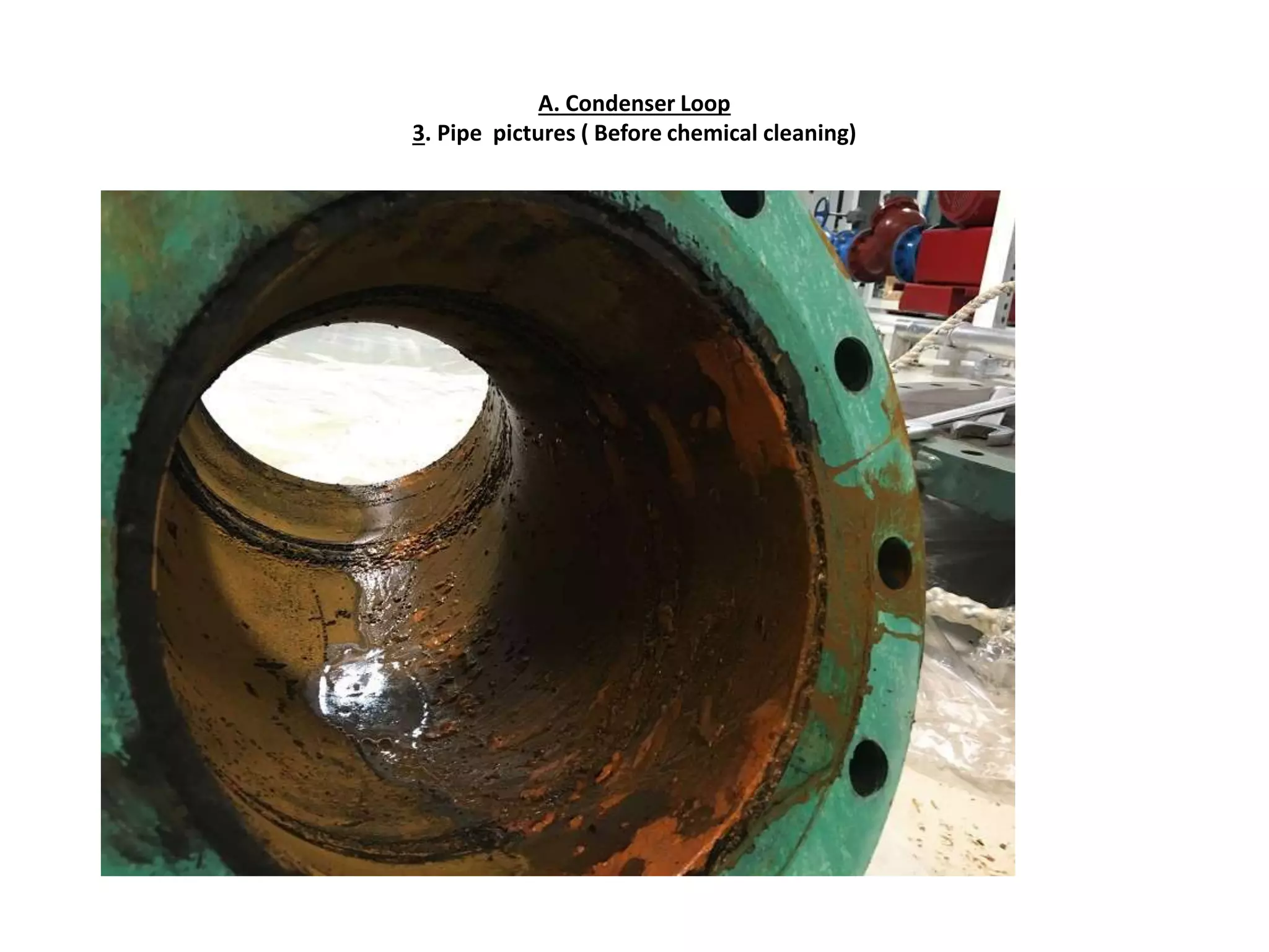
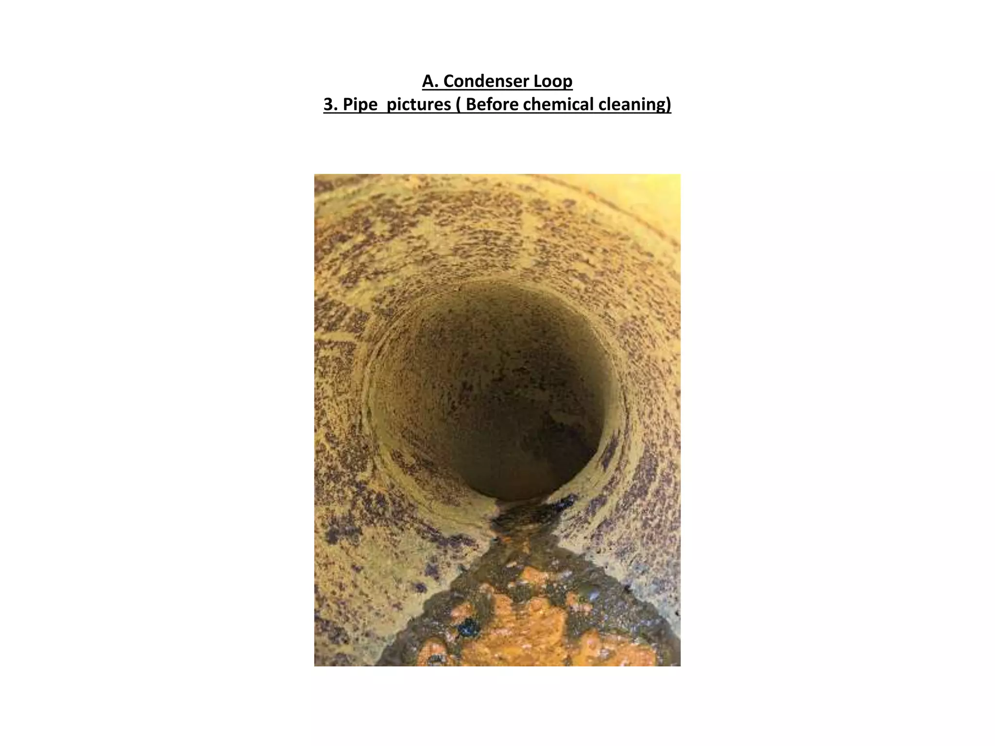
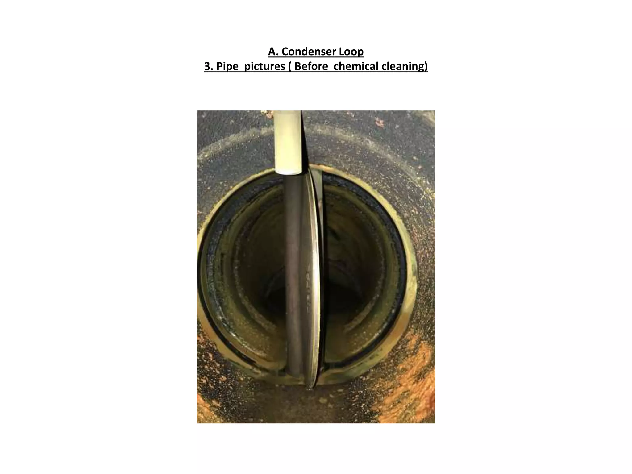
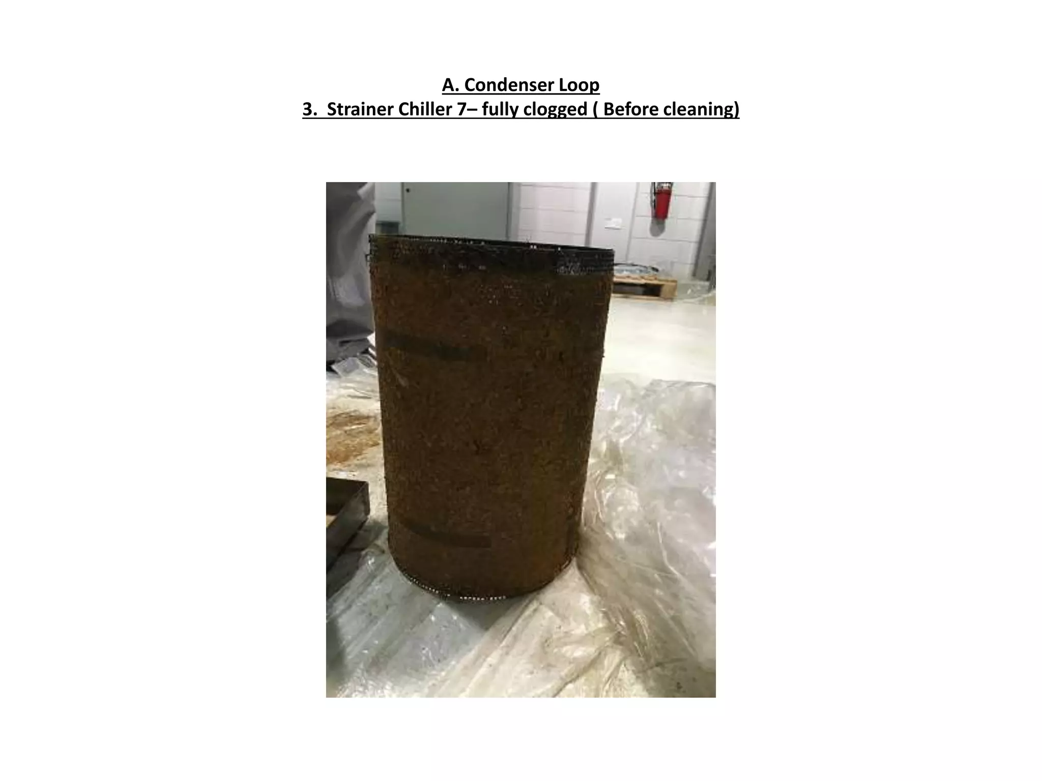
Task order - TO 675
Pictures that highlight the activities/ condition of the components-
before & after the job done
Repair of Chillers 6 & 7 at Combined Utilities Building (CUB) , Bldg 753 NSA II
A. Condenser Loop
Scope of Work 1:
1) Contractor shall open condenser bell caps ( water boxes ) and examine the condition of the
condenser tubes and piping with a camera probe. Copy of the finding and video footage are
to be reported and submitted to the Government
Action Taken :
• Opened Condenser bell caps ( water boxes ) and examined the condition of the condenser
tubes and piping with a camera probe( Video scope)
• The resultant pictures are shown in the following pages of this Presentation. The video scope
recordings are separately given in the CD
• The condenser loop piping were found with loose and hard scale, the strainers were found
clogged fully with contamination. The condenser water boxes / bell caps were found coated
with slurry and other loose scales. The condenser tubes were examined with video scope and
found deposits of loose particles and sediments
A. Condenser Loop
1. Condenser Bell Cap / water boxes pictures ( Before cleaning )
Condenser Tube Sheet
A. Condenser Loop
1. Condenser Bell Cap / water boxes pictures ( Before cleaning )
Condenser Bell Cap
A. Condenser Loop
1. Condenser Bell Cap / water boxes pictures ( Before cleaning )
Condenser Tube sheet
A. Condenser Loop
1. Condenser Bell Cap / water boxes pictures ( Before cleaning )
Condenser Tube sheet & Water Boxes
A. Condenser Loop
1. Condenser Bell Cap / water boxes pictures ( Before cleaning )
Condenser water box
A. Condenser Loop
1. Condenser Bell Cap / water boxes pictures ( Before cleaning )
Condenser water box with outlet pipe view
A. Condenser Loop
1. Condenser Bell Cap / water boxes pictures ( Before cleaning )
Condenser tube sheet
A. Condenser Loop
1. Condenser Bell Cap / water boxes pictures ( Before cleaning )
A. Condenser Loop
1. Condenser Bell Cap / water boxes pictures ( Before cleaning )
A. Condenser Loop
1. Condenser Bell Cap / water boxes pictures ( Before cleaning )
A. Condenser Loop
1. Condenser Bell Cap / water boxes pictures ( Before cleaning )
A. Condenser Loop
1. Tube examination with vedioscope
A. Condenser Loop
1. Tube Internal View- video scope
Tube internal view – video scope ( shown in the link is of a single tube
The balance video scope movies are saved in the CD)
Double-click on AVI
A. Condenser Loop
Scope of Work 2:
2. Contractor shall perform brush cleaning of the condenser tubes
Action Taken :
• Brush cleaned the condenser tubes of Chiller 6 & 7.
• Cleaned the bell caps / water boxes by mechanical means .
• Painted the bell caps / water boxes with epoxy paint
• The following Pictures shows the process
A. Condenser Loop
2. Brush Cleaning of the condenser tubes – Chiller 6
A. Condenser Loop
2. Brush Cleaning of the condenser tubes –Chiller 6
A. Condenser Loop
2. Brush Cleaning of the condenser tubes –Chiller 6
A. Condenser Loop
2. Brush Cleaning of the condenser tubes – Chiller 7
A. Condenser Loop
2. Brush Cleaning of the condenser tubes – Chiller 7
A. Condenser Loop
2. Brush Cleaning of the condenser tubes
A. Condenser Loop
2. Brush Cleaning of the condenser tubes- contamination passing out of the tubes
A. Condenser Loop
2. Brush Cleaning of the condenser tubes- contamination passing out of the tubes
A. Condenser Loop
2. Brush Cleaning of the condenser tubes- contamination collected at the tray
A. Condenser Loop
Scope of Work 3:
1) Contractor shall perform chemical flushing and circulate the chemical thru’ condenser loop and Cooling
Towers on units 6&7
Action Taken :
• Condenser loops of Chiller 6 & 7 were chemical flushed and chemical circulated until the pipes and
accessories were fully cleaned of all contaminations. The cooling tower sump, nozzles , screen of Unit 6
& 7 were cleaned to remove the contaminations .
• The chemical used were NSF approved chemicals . MSDS of chemicals were submitted for approval
• Disposal of the waste chemical were done as per the Bahrain Environmental regulation.
• Cleaned and Painted the Water Boxes/ Bell Caps with Eoxy Paint
• The following Pictures shows the pipe internal coating / deposits prior to the cleaning and after the
chemical cleaning .
A. Condenser Loop
3. Pipe pictures ( Before chemical cleaning )
A. Condenser Loop
3. Pipe pictures ( Before chemical cleaning)
A. Condenser Loop
3. Pipe pictures ( Before chemical cleaning)
A. Condenser Loop
3. Pipe pictures ( Before chemical cleaning)
A. Condenser Loop
3. Pipe pictures ( Before chemical cleaning)
A. Condenser Loop
3. Pipe pictures ( Before chemical cleaning)
A. Condenser Loop
3. Pipe pictures ( Before cleaning)
A. Condenser Loop
3. Pipe pictures ( Before chemical cleaning)
A. Condenser Loop
3. Pipe pictures ( Before chemical cleaning)
A. Condenser Loop
3. Pipe pictures ( Before chemical cleaning)
A. Condenser Loop
3. Pipe pictures ( Before chemical cleaning)
A. Condenser Loop
3. Pipe pictures ( Before chemical cleaning)
A. Condenser Loop
3. Pipe pictures ( Before chemical cleaning)
A. Condenser Loop
3. Strainer Chiller 7– fully clogged ( Before cleaning)
A. Condenser Loop
3. Bucket Strainer Chiller 6 – fully clogged ( Before cleaning)
A. Condenser Loop
3. Pipe pictures ( Before chemical cleaning)
A. Condenser Loop
3. Pipe pictures ( Before chemical cleaning)
A. Condenser Loop
3. Condenser Tube Sheet pictures ( Before cleaning)
A. Condenser Loop
Cooling Tower # 6 before cleaning
A. Condenser Loop
Cooling Tower # 6 before cleaning
A. Condenser Loop
Cooling Tower # 7 before cleaning
A. Condenser Loop
Cooling Tower # 7 before cleaning
A. Condenser Loop
Cooling Tower # 6 before cleaning
A. Condenser Loop
3. Chemical flushing & Cleaning
Chemical Circulation
A. Condenser Loop
3. Chemical flushing & Cleaning
Chemical Circulation
A. Condenser Loop
3. Chemical flushing & Cleaning
Chemical Circulation
A. Condenser Loop
3. Chemical flushing & Cleaning
Chemical Circulation
Tank
A. Condenser Loop
3. Chemical flushing & Cleaning
Chemical Circulation
A. Condenser Loop
3.Piping after chemical cleaning
A. Condenser Loop
3.Piping after chemical cleaning
A. Condenser Loop
3.Pipe Interior after Chemical cleaning
A. Condenser Loop
3.Pump Strainer after chemical cleaning
A. Condenser Loop
3.Bucket Strainer Housing after chemical cleaning
A. Condenser Loop
3.Piping after chemical cleaning
A. Condenser Loop
3. Bucket Strainer Housing after chemical cleaning- Chiller 6
A. Condenser Loop
3.Piping after chemical cleaning
A. Condenser Loop
3.Piping after chemical cleaning
A. Condenser Loop
3.Bucket Strainer Housing after chemical cleaning - Chiller 7
A. Condenser Loop
3.Bucket Strainer after chemical cleaning- Chiller 7
A. Condenser Loop
3.Cooling Tower screen after chemical cleaning
A. Condenser Loop
3.expansion joint after chemical cleaning
A. Condenser Loop
3.cooling tower 6 after cleaning
A. Condenser Loop
3.Cooling Tower 6 after cleaning
A. Condenser Loop
3.Cooling Tower 7 after cleaning
A. Condenser Loop
3.Cooling Tower after chemical cleaning
A. Condenser Loop
3.Condenser water box after cleaning –Chiller 6
A. Condenser Loop
3.Condenser Water Box /Bell caps after cleaning – Chiller 7
A. Condenser Loop
3.Condenser end bell cap after cleaning – chiller 6
A. Condenser Loop
3.Condenser Tube sheet after cleaning – chiller 6
A. Condenser Loop
3.Condenser Bell Cap painted with epoxy paint – chiller 6
A. Condenser Loop
3.Condenser Tube Sheet painted with epoxy paint – chiller 6
A. Condenser Loop
3.Condenser Water Box painted with epoxy paint – chiller 6
A. Condenser Loop
3.Condenser Bell Cap painted with epoxy paint – chiller 7
A. Condenser Loop
3.Condenser Water Box painted with epoxy paint – chiller 7
A. Condenser Loop
3.Condenser Water Box painted with epoxy paint – chiller 7
A. Condenser Loop
3.Condenser Tube Sheet painted with epoxy paint – chiller 7
A. Condenser Loop
Scope of Work 8:
2. Contractor shall properly connect Cooling Tower Fan Motor Gear Box Lubrication piping fittings to rectify
Oil leakages on Cooling Tower 6 & 7
Action Taken :
• Drain the oil , disconnected and removed the lube oil piping fittings , connected back by piping thread
sealant.
• Replaced the flexible hose with hydraulic flexible hose and with hydraulic fittings
• The above job done for both 6 & 7 cooling towers
• The following Pictures shows the new fittings that are leak free
A. Condenser Loop
8. Renewed Lube Oil Piping fittings
A. Condenser Loop
8. Renewed Lube Oil Piping fittings
A. Condenser Loop
8. Renewed Lube Oil Piping fittings
A. Condenser Loop
8. Renewed Lube Oil Piping fittings
. Condenser Loop
8. Renewed Lube Oil Piping fittings
A. Condenser Loop
8. Renewed Lube Oil Piping fittings
A. Condenser Loop
Scope of Work 9:
Contractor shall repair the Cooling Tower Pumps CTP-D-2 so that it will not make any abnormal noise
Action Taken :
• Test run the pump, identified bearing noise for the motor. Disconnected the motor from the drive
coupling , dismantled and replaced both side bearing with new bearings
• Assembled the motor, connected the motor to the drive coupling , carried out alignment checks , test
run and found no abnormal noise.
• The following Pictures shows the bearing replacement for the pump motor
A. Condenser Loop
9. Cooling Tower Pump CTP-D-2 with abnormal noise
Replacement of Motor Bearing with new Bearing
A. Condenser Loop
9. Cooling Tower Pump CTP-D-2 with abnormal noise
Replacement of Motor Bearing with new Bearing
A. Condenser Loop
9. Cooling Tower Pump CTP-D-2 with abnormal noise
Replacement of Motor Bearing with new Bearing
A. Condenser Loop
9. Cooling Tower Pump CTP-D-2 with abnormal noise
Replacement of Motor Bearing with new Bearing
A. Condenser Loop
9. Cooling Tower Pump CTP-D-2 with abnormal noise
Vibration check for motor
A. Condenser Loop
Scope of Work 10:
2. Contractor shall supply and Install Magnetic Sensors ( Vibration Sensors) on Cooling Tower Pumps CTP-D-2
and CTP-D-3
Action Taken :
• Procured i-Alert ( Brand ITT Bell & Gosset Pump) magnetic vibration sensors and installed on the
Pumps
• Tested the function of the i-Alert sensors and found normal functioning
• The following Pictures shows the sensors installed
A. Condenser Loop
10. Missing Magnetic Sensor/ Vibration sensor on CHW Pump CWP-D3
A. Condenser Loop
10. Magnetic Sensor/ Vibration sensor installed on CHW Pump CWP-D3
A. Condenser Loop
10. Missing Magnetic Sensor/ Vibration sensor on CHW Pump CWP-D2
A. Condenser Loop
10. Magnetic Sensor/ Vibration sensor installed on CHW Pump CWP-D2
A. Condenser Loop
Scope of Work 11:
Contractor shall perform laser alignment on all pumps related to the Chiller unit 6 & 7 ( 4 pumps)
Action Taken :
• Conducted Alignment Checks on the pumps of Chiller 6 & 7 .
• Corrected the alignment of Cooling Tower Pump CTP- D-2
• The following Pictures shows the alignment check procedures
A. Condenser Loop
11. Pump Alignment Test
A. Condenser Loop
11. Pump Alignment Test
A. Condenser Loop
11. Pump Alignment Test
A. Condenser Loop
11. Pump Alignment Test
A. Condenser Loop
Scope of Job 12.
• Contractor shall supply a Chemical Cleaning Skid which shall be used to chemically clean all chillers as
necessary
Action Taken :
• Supplied Chemical Cleaning Skid
• Delivered to the CUB
B. Refrigerant Loop
Scope of Job 1.
• Contractor shall recover and recycle the Refrigerant on Chillers 6 & 7 to get rid of the contamination
Action Taken :
• Recovered the refrigerant from the Chiller 6 & 7
• Flushed the refrigerant loop with nitrogen, removed trapped debris / contaminations from the loop
• Vacuum the loop
• Recycled the refrigerant thru’ filter driers for further removal of contaminations
• The following pictures show the procedures
B. Refrigerant Loop
1. Refrigerant Recovery
B. Refrigerant Loop
1. Refrigerant Recovery
B. Refrigerant Loop
1. Flushing the refrigerant loop with nitrogen to get rid of the contamination / debris
B. Refrigerant Loop
1. Flushing the refrigerant loop with nitrogen to get rid of the contamination / debris
debris removed from chiller 7
B. Refrigerant Loop
1. Flushing the refrigerant loop with nitrogen to get rid of the contamination / debris
debris removed from chiller 6
B. Refrigerant Loop
1. Vacuum creation prior to Refrigerant recycle
Vacuum Pump operation in progress
B. Refrigerant Loop
1. Vacuum creation prior to Refrigerant recycle
Vacuum gauge showing the vacuum condition in the refrigerant loop
B. Refrigerant Loop
1. Refrigerant Recycle thru’ filter driers
B. Refrigerant Loop
1. Refrigerant Recycle Process
B. Refrigerant Loop
1. Refrigerant recycle
Oil Filling
B. Refrigerant Loop
1. Refrigerant Recovery
B. Refrigerant Loop
1. Refrigerant Recovery
B. Refrigerant Loop
1. Refrigerant Recycle
Refrigerant liquid level in the sight glass- clear refrigerant without contamination
B. Refrigerant Loop
1. Refrigerant Recycle
Refrigerant liquid level in the sight glass- clear refrigerant without contamination
B. Refrigerant Loop
Scope of Work 2:
Contractor shall replace the Oil Filter, Oil and dehydrator of Chiller unit 6 & 7
Action Taken :
• Replaced the Oil Filter, Oil and Dehydrators of Chiller 6 & 7 .
• Leak tested the joints / fittings, Observed the Oil level . Found normal
• The following Pictures shows the process conducted
B. Refrigerant Loop
2. Replacement of Oil Filter – Chiller 6
B. Refrigerant Loop
2. Replacement of Oil Filter – Chiller 6
B. Refrigerant Loop
2. Replacement of dehydrator – Chiller 6
B. Refrigerant Loop
2. Replacement of dehydrator – Chiller 7
B. Refrigerant Loop
2. Replacement of Oil Filter – Chiller 7
B. Refrigerant Loop
2. Replacement of Oil Filter – Chiller 7
B. Refrigerant Loop
2. Replacement of Oil Filter – Chiller 7
B. Refrigerant Loop
2. Replacement of Oil Filter – Chiller 7
B. Refrigerant Loop
2. Replacement of Oil Filter – Chiller 7
B. Refrigerant Loop
2. Replacement of Oil Filter – Chiller 7
B. Refrigerant Loop
Scope of Work 3:
Contractor shall rectify the faulty differential pressure switches on Chiller unit 6 & 7
Action Taken :
• Rectified the faulty differential switches of Chiller 6 & 7 .
• The following Pictures shows the testing and setting up of DPS
B. Refrigerant Loop
3. Differential Pressure Switch Setting – Chiller 7
B. Refrigerant Loop
3. Differential Pressure Switch Setting – Chiller 7
C. Distribution Pumps and Schneider Control System
Scope of Job 1:
Contractor shall perform laser alignment on Distribution Pumps DP-D-1 and DP-J-1
Action Taken :
• Tested the drive coupling alignment of Distribution Pumps DP-D-1 and DP-J-1
• Corrected the misalignment on DP-J-1
C. Distribution Pumps and Schneider Control System
1. Distribution Pump alignment test
C. Distribution Pumps and Schneider Control System
Scope of Job 2:
Contractor shall investigate and rectify the cause of system short cycling in the Schneider Programming.
Action Taken :
• The sequencing of the chillers and its ancillary units were tested and the control parameter of the
return chilled water temperature set point was found below the design of 12.2 c .
• Reset the control to 12.2 C.
• Observed the system for proper sequencing without short cycle. Found normal

Chiller repair, condenser & refrigerant loop test, pump alignment, videoscope

  • 1.
    Task order -TO 675 Pictures that highlight the activities/ condition of the components- before & after the job done Repair of Chillers 6 & 7 at Combined Utilities Building (CUB) , Bldg 753 NSA II
  • 2.
    A. Condenser Loop Scopeof Work 1: 1) Contractor shall open condenser bell caps ( water boxes ) and examine the condition of the condenser tubes and piping with a camera probe. Copy of the finding and video footage are to be reported and submitted to the Government Action Taken : • Opened Condenser bell caps ( water boxes ) and examined the condition of the condenser tubes and piping with a camera probe( Video scope) • The resultant pictures are shown in the following pages of this Presentation. The video scope recordings are separately given in the CD • The condenser loop piping were found with loose and hard scale, the strainers were found clogged fully with contamination. The condenser water boxes / bell caps were found coated with slurry and other loose scales. The condenser tubes were examined with video scope and found deposits of loose particles and sediments
  • 3.
    A. Condenser Loop 1.Condenser Bell Cap / water boxes pictures ( Before cleaning ) Condenser Tube Sheet
  • 4.
    A. Condenser Loop 1.Condenser Bell Cap / water boxes pictures ( Before cleaning ) Condenser Bell Cap
  • 5.
    A. Condenser Loop 1.Condenser Bell Cap / water boxes pictures ( Before cleaning ) Condenser Tube sheet
  • 6.
    A. Condenser Loop 1.Condenser Bell Cap / water boxes pictures ( Before cleaning ) Condenser Tube sheet & Water Boxes
  • 7.
    A. Condenser Loop 1.Condenser Bell Cap / water boxes pictures ( Before cleaning ) Condenser water box
  • 8.
    A. Condenser Loop 1.Condenser Bell Cap / water boxes pictures ( Before cleaning ) Condenser water box with outlet pipe view
  • 9.
    A. Condenser Loop 1.Condenser Bell Cap / water boxes pictures ( Before cleaning ) Condenser tube sheet
  • 10.
    A. Condenser Loop 1.Condenser Bell Cap / water boxes pictures ( Before cleaning )
  • 11.
    A. Condenser Loop 1.Condenser Bell Cap / water boxes pictures ( Before cleaning )
  • 12.
    A. Condenser Loop 1.Condenser Bell Cap / water boxes pictures ( Before cleaning )
  • 13.
    A. Condenser Loop 1.Condenser Bell Cap / water boxes pictures ( Before cleaning )
  • 14.
    A. Condenser Loop 1.Tube examination with vedioscope
  • 15.
    A. Condenser Loop 1.Tube Internal View- video scope Tube internal view – video scope ( shown in the link is of a single tube The balance video scope movies are saved in the CD) Double-click on AVI
  • 16.
    A. Condenser Loop Scopeof Work 2: 2. Contractor shall perform brush cleaning of the condenser tubes Action Taken : • Brush cleaned the condenser tubes of Chiller 6 & 7. • Cleaned the bell caps / water boxes by mechanical means . • Painted the bell caps / water boxes with epoxy paint • The following Pictures shows the process
  • 17.
    A. Condenser Loop 2.Brush Cleaning of the condenser tubes – Chiller 6
  • 18.
    A. Condenser Loop 2.Brush Cleaning of the condenser tubes –Chiller 6
  • 19.
    A. Condenser Loop 2.Brush Cleaning of the condenser tubes –Chiller 6
  • 20.
    A. Condenser Loop 2.Brush Cleaning of the condenser tubes – Chiller 7
  • 21.
    A. Condenser Loop 2.Brush Cleaning of the condenser tubes – Chiller 7
  • 22.
    A. Condenser Loop 2.Brush Cleaning of the condenser tubes
  • 23.
    A. Condenser Loop 2.Brush Cleaning of the condenser tubes- contamination passing out of the tubes
  • 24.
    A. Condenser Loop 2.Brush Cleaning of the condenser tubes- contamination passing out of the tubes
  • 25.
    A. Condenser Loop 2.Brush Cleaning of the condenser tubes- contamination collected at the tray
  • 26.
    A. Condenser Loop Scopeof Work 3: 1) Contractor shall perform chemical flushing and circulate the chemical thru’ condenser loop and Cooling Towers on units 6&7 Action Taken : • Condenser loops of Chiller 6 & 7 were chemical flushed and chemical circulated until the pipes and accessories were fully cleaned of all contaminations. The cooling tower sump, nozzles , screen of Unit 6 & 7 were cleaned to remove the contaminations . • The chemical used were NSF approved chemicals . MSDS of chemicals were submitted for approval • Disposal of the waste chemical were done as per the Bahrain Environmental regulation. • Cleaned and Painted the Water Boxes/ Bell Caps with Eoxy Paint • The following Pictures shows the pipe internal coating / deposits prior to the cleaning and after the chemical cleaning .
  • 27.
    A. Condenser Loop 3.Pipe pictures ( Before chemical cleaning )
  • 28.
    A. Condenser Loop 3.Pipe pictures ( Before chemical cleaning)
  • 29.
    A. Condenser Loop 3.Pipe pictures ( Before chemical cleaning)
  • 30.
    A. Condenser Loop 3.Pipe pictures ( Before chemical cleaning)
  • 31.
    A. Condenser Loop 3.Pipe pictures ( Before chemical cleaning)
  • 32.
    A. Condenser Loop 3.Pipe pictures ( Before chemical cleaning)
  • 33.
    A. Condenser Loop 3.Pipe pictures ( Before cleaning)
  • 34.
    A. Condenser Loop 3.Pipe pictures ( Before chemical cleaning)
  • 35.
    A. Condenser Loop 3.Pipe pictures ( Before chemical cleaning)
  • 36.
    A. Condenser Loop 3.Pipe pictures ( Before chemical cleaning)
  • 37.
    A. Condenser Loop 3.Pipe pictures ( Before chemical cleaning)
  • 38.
    A. Condenser Loop 3.Pipe pictures ( Before chemical cleaning)
  • 39.
    A. Condenser Loop 3.Pipe pictures ( Before chemical cleaning)
  • 40.
    A. Condenser Loop 3.Strainer Chiller 7– fully clogged ( Before cleaning)
  • 41.
    A. Condenser Loop 3.Bucket Strainer Chiller 6 – fully clogged ( Before cleaning)
  • 42.
    A. Condenser Loop 3.Pipe pictures ( Before chemical cleaning)
  • 43.
    A. Condenser Loop 3.Pipe pictures ( Before chemical cleaning)
  • 44.
    A. Condenser Loop 3.Condenser Tube Sheet pictures ( Before cleaning)
  • 45.
    A. Condenser Loop CoolingTower # 6 before cleaning
  • 46.
    A. Condenser Loop CoolingTower # 6 before cleaning
  • 47.
    A. Condenser Loop CoolingTower # 7 before cleaning
  • 48.
    A. Condenser Loop CoolingTower # 7 before cleaning
  • 49.
    A. Condenser Loop CoolingTower # 6 before cleaning
  • 50.
    A. Condenser Loop 3.Chemical flushing & Cleaning Chemical Circulation
  • 51.
    A. Condenser Loop 3.Chemical flushing & Cleaning Chemical Circulation
  • 52.
    A. Condenser Loop 3.Chemical flushing & Cleaning Chemical Circulation
  • 53.
    A. Condenser Loop 3.Chemical flushing & Cleaning Chemical Circulation Tank
  • 54.
    A. Condenser Loop 3.Chemical flushing & Cleaning Chemical Circulation
  • 55.
    A. Condenser Loop 3.Pipingafter chemical cleaning
  • 56.
    A. Condenser Loop 3.Pipingafter chemical cleaning
  • 57.
    A. Condenser Loop 3.PipeInterior after Chemical cleaning
  • 58.
    A. Condenser Loop 3.PumpStrainer after chemical cleaning
  • 59.
    A. Condenser Loop 3.BucketStrainer Housing after chemical cleaning
  • 60.
    A. Condenser Loop 3.Pipingafter chemical cleaning
  • 61.
    A. Condenser Loop 3.Bucket Strainer Housing after chemical cleaning- Chiller 6
  • 62.
    A. Condenser Loop 3.Pipingafter chemical cleaning
  • 63.
    A. Condenser Loop 3.Pipingafter chemical cleaning
  • 64.
    A. Condenser Loop 3.BucketStrainer Housing after chemical cleaning - Chiller 7
  • 65.
    A. Condenser Loop 3.BucketStrainer after chemical cleaning- Chiller 7
  • 66.
    A. Condenser Loop 3.CoolingTower screen after chemical cleaning
  • 67.
    A. Condenser Loop 3.expansionjoint after chemical cleaning
  • 68.
    A. Condenser Loop 3.coolingtower 6 after cleaning
  • 69.
    A. Condenser Loop 3.CoolingTower 6 after cleaning
  • 70.
    A. Condenser Loop 3.CoolingTower 7 after cleaning
  • 71.
    A. Condenser Loop 3.CoolingTower after chemical cleaning
  • 72.
    A. Condenser Loop 3.Condenserwater box after cleaning –Chiller 6
  • 73.
    A. Condenser Loop 3.CondenserWater Box /Bell caps after cleaning – Chiller 7
  • 74.
    A. Condenser Loop 3.Condenserend bell cap after cleaning – chiller 6
  • 75.
    A. Condenser Loop 3.CondenserTube sheet after cleaning – chiller 6
  • 76.
    A. Condenser Loop 3.CondenserBell Cap painted with epoxy paint – chiller 6
  • 77.
    A. Condenser Loop 3.CondenserTube Sheet painted with epoxy paint – chiller 6
  • 78.
    A. Condenser Loop 3.CondenserWater Box painted with epoxy paint – chiller 6
  • 79.
    A. Condenser Loop 3.CondenserBell Cap painted with epoxy paint – chiller 7
  • 80.
    A. Condenser Loop 3.CondenserWater Box painted with epoxy paint – chiller 7
  • 81.
    A. Condenser Loop 3.CondenserWater Box painted with epoxy paint – chiller 7
  • 82.
    A. Condenser Loop 3.CondenserTube Sheet painted with epoxy paint – chiller 7
  • 83.
    A. Condenser Loop Scopeof Work 8: 2. Contractor shall properly connect Cooling Tower Fan Motor Gear Box Lubrication piping fittings to rectify Oil leakages on Cooling Tower 6 & 7 Action Taken : • Drain the oil , disconnected and removed the lube oil piping fittings , connected back by piping thread sealant. • Replaced the flexible hose with hydraulic flexible hose and with hydraulic fittings • The above job done for both 6 & 7 cooling towers • The following Pictures shows the new fittings that are leak free
  • 84.
    A. Condenser Loop 8.Renewed Lube Oil Piping fittings
  • 85.
    A. Condenser Loop 8.Renewed Lube Oil Piping fittings
  • 86.
    A. Condenser Loop 8.Renewed Lube Oil Piping fittings
  • 87.
    A. Condenser Loop 8.Renewed Lube Oil Piping fittings
  • 88.
    . Condenser Loop 8.Renewed Lube Oil Piping fittings
  • 89.
    A. Condenser Loop 8.Renewed Lube Oil Piping fittings
  • 90.
    A. Condenser Loop Scopeof Work 9: Contractor shall repair the Cooling Tower Pumps CTP-D-2 so that it will not make any abnormal noise Action Taken : • Test run the pump, identified bearing noise for the motor. Disconnected the motor from the drive coupling , dismantled and replaced both side bearing with new bearings • Assembled the motor, connected the motor to the drive coupling , carried out alignment checks , test run and found no abnormal noise. • The following Pictures shows the bearing replacement for the pump motor
  • 91.
    A. Condenser Loop 9.Cooling Tower Pump CTP-D-2 with abnormal noise Replacement of Motor Bearing with new Bearing
  • 92.
    A. Condenser Loop 9.Cooling Tower Pump CTP-D-2 with abnormal noise Replacement of Motor Bearing with new Bearing
  • 93.
    A. Condenser Loop 9.Cooling Tower Pump CTP-D-2 with abnormal noise Replacement of Motor Bearing with new Bearing
  • 94.
    A. Condenser Loop 9.Cooling Tower Pump CTP-D-2 with abnormal noise Replacement of Motor Bearing with new Bearing
  • 95.
    A. Condenser Loop 9.Cooling Tower Pump CTP-D-2 with abnormal noise Vibration check for motor
  • 96.
    A. Condenser Loop Scopeof Work 10: 2. Contractor shall supply and Install Magnetic Sensors ( Vibration Sensors) on Cooling Tower Pumps CTP-D-2 and CTP-D-3 Action Taken : • Procured i-Alert ( Brand ITT Bell & Gosset Pump) magnetic vibration sensors and installed on the Pumps • Tested the function of the i-Alert sensors and found normal functioning • The following Pictures shows the sensors installed
  • 97.
    A. Condenser Loop 10.Missing Magnetic Sensor/ Vibration sensor on CHW Pump CWP-D3
  • 98.
    A. Condenser Loop 10.Magnetic Sensor/ Vibration sensor installed on CHW Pump CWP-D3
  • 99.
    A. Condenser Loop 10.Missing Magnetic Sensor/ Vibration sensor on CHW Pump CWP-D2
  • 100.
    A. Condenser Loop 10.Magnetic Sensor/ Vibration sensor installed on CHW Pump CWP-D2
  • 101.
    A. Condenser Loop Scopeof Work 11: Contractor shall perform laser alignment on all pumps related to the Chiller unit 6 & 7 ( 4 pumps) Action Taken : • Conducted Alignment Checks on the pumps of Chiller 6 & 7 . • Corrected the alignment of Cooling Tower Pump CTP- D-2 • The following Pictures shows the alignment check procedures
  • 102.
    A. Condenser Loop 11.Pump Alignment Test
  • 103.
    A. Condenser Loop 11.Pump Alignment Test
  • 104.
    A. Condenser Loop 11.Pump Alignment Test
  • 105.
    A. Condenser Loop 11.Pump Alignment Test
  • 106.
    A. Condenser Loop Scopeof Job 12. • Contractor shall supply a Chemical Cleaning Skid which shall be used to chemically clean all chillers as necessary Action Taken : • Supplied Chemical Cleaning Skid • Delivered to the CUB
  • 107.
    B. Refrigerant Loop Scopeof Job 1. • Contractor shall recover and recycle the Refrigerant on Chillers 6 & 7 to get rid of the contamination Action Taken : • Recovered the refrigerant from the Chiller 6 & 7 • Flushed the refrigerant loop with nitrogen, removed trapped debris / contaminations from the loop • Vacuum the loop • Recycled the refrigerant thru’ filter driers for further removal of contaminations • The following pictures show the procedures
  • 108.
    B. Refrigerant Loop 1.Refrigerant Recovery
  • 109.
    B. Refrigerant Loop 1.Refrigerant Recovery
  • 110.
    B. Refrigerant Loop 1.Flushing the refrigerant loop with nitrogen to get rid of the contamination / debris
  • 111.
    B. Refrigerant Loop 1.Flushing the refrigerant loop with nitrogen to get rid of the contamination / debris debris removed from chiller 7
  • 112.
    B. Refrigerant Loop 1.Flushing the refrigerant loop with nitrogen to get rid of the contamination / debris debris removed from chiller 6
  • 113.
    B. Refrigerant Loop 1.Vacuum creation prior to Refrigerant recycle Vacuum Pump operation in progress
  • 114.
    B. Refrigerant Loop 1.Vacuum creation prior to Refrigerant recycle Vacuum gauge showing the vacuum condition in the refrigerant loop
  • 115.
    B. Refrigerant Loop 1.Refrigerant Recycle thru’ filter driers
  • 116.
    B. Refrigerant Loop 1.Refrigerant Recycle Process
  • 117.
    B. Refrigerant Loop 1.Refrigerant recycle Oil Filling
  • 118.
    B. Refrigerant Loop 1.Refrigerant Recovery
  • 119.
    B. Refrigerant Loop 1.Refrigerant Recovery
  • 120.
    B. Refrigerant Loop 1.Refrigerant Recycle Refrigerant liquid level in the sight glass- clear refrigerant without contamination
  • 121.
    B. Refrigerant Loop 1.Refrigerant Recycle Refrigerant liquid level in the sight glass- clear refrigerant without contamination
  • 122.
    B. Refrigerant Loop Scopeof Work 2: Contractor shall replace the Oil Filter, Oil and dehydrator of Chiller unit 6 & 7 Action Taken : • Replaced the Oil Filter, Oil and Dehydrators of Chiller 6 & 7 . • Leak tested the joints / fittings, Observed the Oil level . Found normal • The following Pictures shows the process conducted
  • 123.
    B. Refrigerant Loop 2.Replacement of Oil Filter – Chiller 6
  • 124.
    B. Refrigerant Loop 2.Replacement of Oil Filter – Chiller 6
  • 125.
    B. Refrigerant Loop 2.Replacement of dehydrator – Chiller 6
  • 126.
    B. Refrigerant Loop 2.Replacement of dehydrator – Chiller 7
  • 127.
    B. Refrigerant Loop 2.Replacement of Oil Filter – Chiller 7
  • 128.
    B. Refrigerant Loop 2.Replacement of Oil Filter – Chiller 7
  • 129.
    B. Refrigerant Loop 2.Replacement of Oil Filter – Chiller 7
  • 130.
    B. Refrigerant Loop 2.Replacement of Oil Filter – Chiller 7
  • 131.
    B. Refrigerant Loop 2.Replacement of Oil Filter – Chiller 7
  • 132.
    B. Refrigerant Loop 2.Replacement of Oil Filter – Chiller 7
  • 133.
    B. Refrigerant Loop Scopeof Work 3: Contractor shall rectify the faulty differential pressure switches on Chiller unit 6 & 7 Action Taken : • Rectified the faulty differential switches of Chiller 6 & 7 . • The following Pictures shows the testing and setting up of DPS
  • 134.
    B. Refrigerant Loop 3.Differential Pressure Switch Setting – Chiller 7
  • 135.
    B. Refrigerant Loop 3.Differential Pressure Switch Setting – Chiller 7
  • 136.
    C. Distribution Pumpsand Schneider Control System Scope of Job 1: Contractor shall perform laser alignment on Distribution Pumps DP-D-1 and DP-J-1 Action Taken : • Tested the drive coupling alignment of Distribution Pumps DP-D-1 and DP-J-1 • Corrected the misalignment on DP-J-1
  • 137.
    C. Distribution Pumpsand Schneider Control System 1. Distribution Pump alignment test
  • 138.
    C. Distribution Pumpsand Schneider Control System Scope of Job 2: Contractor shall investigate and rectify the cause of system short cycling in the Schneider Programming. Action Taken : • The sequencing of the chillers and its ancillary units were tested and the control parameter of the return chilled water temperature set point was found below the design of 12.2 c . • Reset the control to 12.2 C. • Observed the system for proper sequencing without short cycle. Found normal