Downloaded 116 times


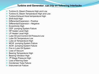
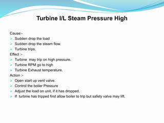

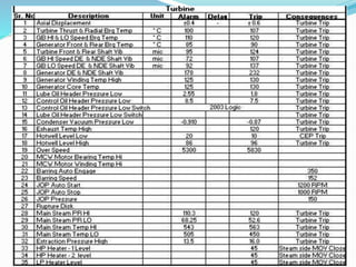

In modern power plants, extensive protections and interlocks are provided to isolate faulty equipment without causing further damage and allow reserve equipment to start up automatically. Protections detect abnormal parameters and trip equipment to prevent major damage. Interlocks make equipment states dependent to prevent incorrect operation. Protections include tripping the turbine for issues like high/low steam pressure, temperature, exhaust hood temperature, axial shift, differential expansion, eccentricity, pump failures, and low lubricating oil pressure.


