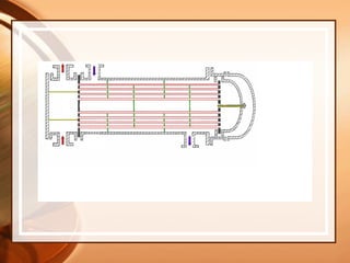
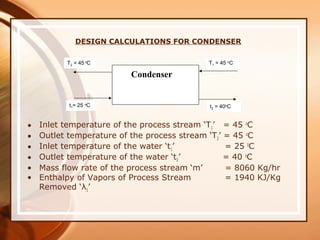
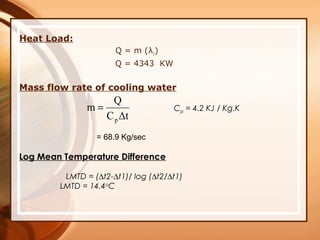
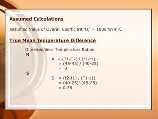
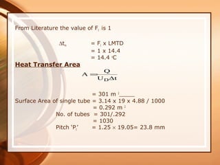
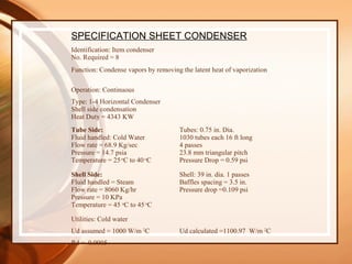
A condenser is a heat exchanger that transfers vapors into a liquid state by removing latent heat with a coolant like water. This document provides design calculations for an 8 unit shell and tube condenser with 1030 tubes that uses cold water as the coolant to condense steam at a rate of 8060 kg/hr and 4343 kW of heat duty. Key specifications are provided, like a calculated overall heat transfer coefficient of 1100.97 W/m2C and pressure drops of 0.59 psi for the tube side and 0.109 psi for the shell side. References on condenser design are also listed.
1. • Introduction
• A condenser is a type of heat exchanger in which
vapors are transferred into liquid state by removing
the latent heat with the help of a coolant such as
water.
• Condensers may be classified into two main types:
1. Those in which the coolant and condensing vapor
are brought into direct contact.
2. Those in which the coolant and condensate stream
are separated by a solid surface, usually a tube
wall
2. Different types of the Condenser
1. Double pipe and multiple pipe
2. Plate Condensers
3. Air-Cooled Condensers
4. Compact Condensers
5. Shell & tube type
3.
4. DESIGN CALCULATIONS FOR CONDENSER
• Inlet temperature of the process stream ‘T1’ = 45 o
C
• Outlet temperature of the process stream ‘T2’ = 45 o
C
• Inlet temperature of the water ‘t1’ = 25 0
C
• Outlet temperature of the water ‘t2’ = 40 o
C
• Mass flow rate of the process stream ‘m’ = 8060 Kg/hr
• Enthalpy of Vapors of Process Stream = 1940 KJ/Kg
Removed ‘λ1’
T2 = 45 o
C
t1= 25 o
C t2 = 40o
C
T1 = 45 o
C
Condenser
5. Heat Load:
Q = m (λ1)
Q = 4343 KW
Mass flow rate of cooling water
ΔtC
Q
m
p
=
= 68.9 Kg/sec
Log Mean Temperature Difference
LMTD = (∆t2-∆t1)/ log (∆t2/∆t1)
LMTD = 14.4o
C
Cp = 4.2 KJ / Kg.K
6. Assumed Calculations
Assumed Value of Overall Coefficient ‘UD’ = 1000 W/m 2
C
True Mean Temperature Difference
Dimensionless Temperature Ratios
R
R = (T1-T2) / (t2-t1)
= (45-45) / (40-25)
= 0
S
S = (t2-t1) / (T1-t1)
= (40-25)/ (45-25)
= 0.75
7. From Literature the value of Ft is 1
∆tm = Ft x LMTD
= 1 x 14.4
= 14.4 o
C
Heat Transfer Area
= 301 m 2
Surface Area of single tube = 3.14 x 19 x 4.88 / 1000
= 0.292 m 2
No. of tubes = 301/.292
= 1030
Pitch ‘Pt’ = 1.25 × 19.05= 23.8 mm
ΔtU
Q
A
D
=
8. Tube Bundle Diameter
Db = d0 (Nt/K1)1/n1
= 19 (1030/0.158)1/2.263
= 920 mm
No. of tubes in centre row
Nr = Db / Pt
= 920 / 23.8
= 39
Shell Side Calculations
Estimate tube wall temperature Tw
Assume condensing coefficient of 4250 W/m2
C (from literature)
Mean Temperature
Shell side =( 45+45) / 2 = 45 o
C
Tube side = (25+40) / 2 = 32.5 o
C
(45-Tw) x 4250 = (45-25) x 1000
Tw = 40.3 o
C
9. Physical Properties
Viscosity of the liquid ‘µL’ = 0.8 mNs/m2
Density of liquid ‘ρL’ = 993 Kg/m3
Thermal conductivity ‘kL’ = 0.571 W/m C
Average M. Wt. of Vapors = 42.8
Density of vapor = 29 x 273 x 1/(22.4 x 1 x (273+42))
= 1.12 Kg / m3
Condensate loading on a horizontal tube ’Ѓh’ = m / L x Nt
= 8060 / 3600 x (4.88 x 1030)
= 4.45 x 10⁻³
Kg/m s
# of tubes in the vertical row ’Nr’ = 2/3 x 39 = 26 mm
Heat transfer coefficient in condensation
‘h0’ = 0.95 x kL ( ρL x (ρL – ρv ) g / (µL x Ѓh)1/3
x Nr-1/6
= 4396.0 W/m2о
C
• As our assumed value is correct so no need to correct the
wall temperature
10. Tube Side Calculations
Tube cross sectional area = 3.14 / 4 x (19 x 10-3
)2 x
1030 / 4
= 0.073 m2
Density of water at 30 0
C = 993 kg/m3
Tube velocity = m / (ρH2O x At )
= 68.9 / (993 x 0.073)
= 0.95m/s
Film heat transfer coefficient inside a tube
‘hi’ = 4200(1.35+0.02 x t) Vt0.8
/ di
. 0 2
= 4809.67 W/m2 0
C
From Literature take fouling factor as 6000 W/m2 0
C
Thermal Conductivity of the tube wall material
‘Kw’ = 50 W/m0
C
11. Overall Coefficient
1/U0 = 1/ho + 1/hod + (d0 ln(d0/di))/2kw +d0/di x 1/hid +d0/di x 1/hi
= 0.001
U0 = 1100.29 W/m2 0
C
So assumed value is correct
12. Shell Side Pressure Drop
For pull through floating head with 45% cut baffles
From literature clearance = 88 mm
Shell internal diameter ‘Ds’ = Db+88
= 1008 mm
Cross flow area ‘As’ = m2
A= 0.205 m2
Mass Velocity
Gt = m / As
= 8060 / (3600 x 0.205)
= 10.92 Kg/s m2
Equivalent diameter ‘de’ = 1.27 (Pt2
-0.785d0
2
) / d0 = 19 mm
Viscosity of vapors ‘µ’ = 0.009 mNs/m2
Reynold’s No.
Re = de Gt / µ
= 19 x 10-3
x 10.92 /0.009 x 10-3
Re = 23053
13. From literature
jf = 0.029
By neglecting the viscosity correction factor
Where
Ds = dia of shell
L = Length of tubes
lB = baffle spacing
So
= 765 N/m2
= 0.765 Kpa
= 0.109 Psi
14. Tube side pressure drop
Viscosity of water ‘µ’ = 0.9 x 10⁻³
Ns/m2
Re = Vt ρ di /µ
= 0.95 x 993 x 16.56 x 10-3
/ 0.6 x 10-3
= 26036
From literature
jf = 0.0039
Where
Np = No. of tube passes
So
∆Pt = 4119.8 N/m2
= 4.119Kpa
= 0.59 psi
Acceptable
15. hio = hi ×I.D/O.D
hio = 4165.2 W/m2 0
C
Clean Overall Coefficient:
= 2138.7 W/m2 0
C
Design Overall Coefficient Calculated
dirt factor Rd = 0.0005
D
D
UU
UU
R
C
C
d
−
=
oio
oio
C
hh
hh
U
+
=
16. SPECIFICATION SHEET CONDENSER
Identification: Item condenser
No. Required = 8
Function: Condense vapors by removing the latent heat of vaporization
Operation: Continuous
Type: 1-4 Horizontal Condenser
Shell side condensation
Heat Duty = 4343 KW
Tube Side:
Fluid handled: Cold Water
Flow rate = 68.9 Kg/sec
Pressure = 14.7 psia
Temperature = 25 o
C to 40 o
C
Tubes: 0.75 in. Dia.
1030 tubes each 16 ft long
4 passes
23.8 mm triangular pitch
Pressure Drop = 0.59 psi
Shell Side:
Fluid handled = Steam
Flow rate = 8060 Kg/hr
Pressure = 10 KPa
Temperature = 45 o
C to 45 o
C
Shell: 39 in. dia. 1 passes
Baffles spacing = 3.5 in.
Pressure drop =0.109 psi
Utilities: Cold water
Ud assumed = 1000 W/m 2
C Ud calculated =1100.97 W/m 2
C
Rd = 0.0005
17. References
• Chemical Engineering Design
Volume 6 by Coulson &v Richardson’s
• Process Heat Transfer
by D.Q. Kern
• Plant Design & Economics for Chemical Engineers
5th
Edition by Max S. Peters, Klaus D. Timmerhaus,
Ronald E. West
• Perry’s Chemical Engineers’ Handbook
by Robert H. Perry, Don. W. Green