Download as PDF, PPTX
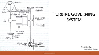


The document discusses turbine governing systems. The objective of turbine governing is to control the steam flow to a turbine to maintain a constant rotation speed as load varies. It describes three common types of governing: throttle, nozzle, and bypass. The key components of a hydro-mechanical governing system are then outlined, including the speed governor, pilot valves, control valves, and emergency shutdown mechanisms. Protection systems using hydraulic and electrical trips are also summarized to safely operate the turbine.


