Downloaded 756 times


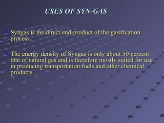


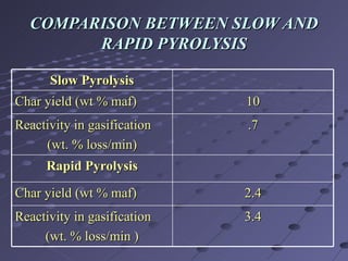


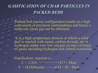


The document discusses a method for producing synthesis gas (syngas) from gasification of bagasse. Bagasse is a waste product from sugar production that is abundant in India. Syngas produced from bagasse gasification can be used as an alternative fuel source for power generation and other industrial processes. The method involves pyrolyzing bagasse in a free-fall reactor to produce char, and then gasifying the char in a packed bed reactor to produce syngas, which consists mainly of carbon monoxide and hydrogen. Experimental results show that syngas yield increases with higher temperature and smaller bagasse particle size during pyrolysis.


