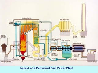
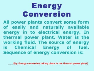
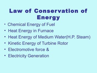
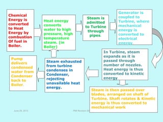
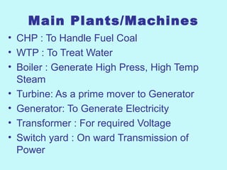
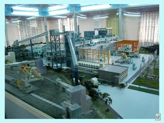
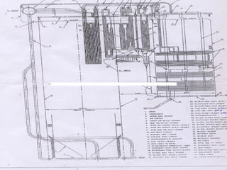
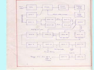
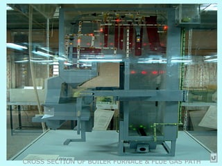
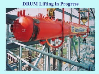
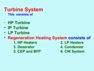
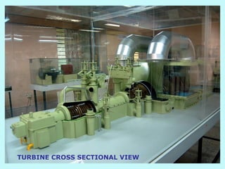
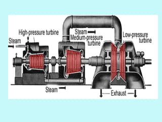
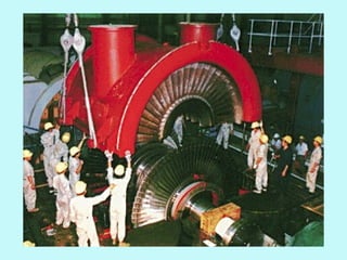
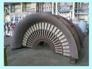
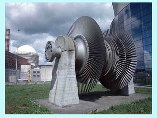
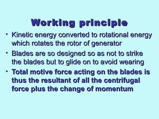
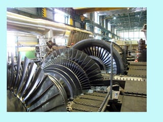
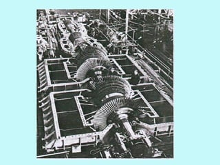
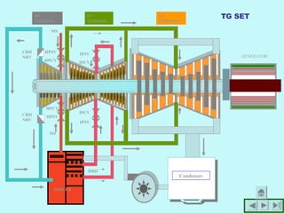
Welcome to presentation on
Thermal Power Generation
Layout of a Pulverized Fuel Power Plant
What is Thermal Power ?
Electricity Generation using
heat value of Fuel
June 29, 2013 4
and naturally available energy in to electrical energy. In thermal power plant, Water is the working fluid. The source of energy is C
Energy
Conversion
All power plants convert some form
of easily and naturally available
energy in to electrical energy. In
thermal power plant, Water is the
working fluid. The source of energy
is Chemical Energy of fuel.
Sequence of energy conversion is:
June 29, 2013
Fig. Energy conversion taking place in the thermal power plant)5
Working Principle
Rankine Cycle
Law of Conservation of
Energy
• Chemical Energy of Fuel
• Heat Energy in Furnace
• Heat Energy of Medium Water(H.P. Steam)
• Kinetic Energy of Turbine Rotor
• Electromotive force &
• Electricity Generation
June 29, 2013 PMI Revision 00 8
Chemical
Energy is
converted
to Heat
Energy by
combustion
Of fuel in
Boiler.
Heat energy
converts
water to high
pressure, high
temperature
steam. (in
Boiler)
In Turbine, steam
expands as it is
passed through
number of nozzles.
Heat energy is thus
converted to kinetic
energy.
Steam is
admitted
to Turbine
through
pipes.
Steam is then passed over
blades, arranged on shaft of
Turbine. Shaft rotates & Kinetic
energy is thus converted to
mechanical work
Steam exhausted
from turbine
condenses in
Condenser,
rejecting
unavailable heat
energy.
Pump
delivers
condensed
water from
Condenser
back to
Boiler.
Generator is
coupled to
Turbine, where
mechanical
energy is
converted to
electrical
energy.
Main Inputs
Water : Medium
Coal : Fuel
June 29, 2013 PMI Revision 00 9
WHY COAL as Fuel
Coal can provide usable energy at a cost
of between 12 to 15 % compared to oil and
natural gas, and coal prices are relatively
stable.
Coal is inherently higher-polluting and
more carbon-intensive than other energy
alternatives.
However, coal is so inexpensive that one
can spend quite a bit on pollution control,
and still maintain coal’s competitive
position.
Main Plants/Machines
• CHP : To Handle Fuel Coal
• WTP : To Treat Water
• Boiler : Generate High Press, High Temp
Steam
• Turbine: As a prime mover to Generator
• Generator: To Generate Electricity
• Transformer : For required Voltage
• Switch yard : On ward Transmission of
Power
TYPES OF WATER REQUIRED
AT TPS
• DEMINERALISED WATER – BOILER
• SOFTEN WATER – COOLING &
GENERAL SERVICE
• DRINKING WATER – DOMESTIC PURPOSE
• ASH HANDLING – RAW WATER OR
UNTREATED WATER
• FIRE FIGHTING – UNTREATED WATER
• COAL HANDLING – UNTREATED WATER
• DM % 3-4
• CW/GS % 50-55
• AHP % 40-45
• DOMESTIC % 6-7
STRUCTURE OF BOILERS
• Boiler structure is supported on 4 columns that is hung from
top and supported on vertical columns
• Boiler is of tangentially fired balanced draught natural
circulating radiant reheat cycle dry bottom with direct
pulverized coal type
• All plates, rivets, bars and their testing is covered under
regulation and construction is done under the supervision of
inspecting officer at all the stages
• Total expansion of boiler vertically downwards in heated
condition is 340 mm and ideal expansion is 1.2 mm/mtr/1000
C
• Seal through and bottom ash hoppers is provided
Boiler System
This system consists of
• Furnace System
• Super Heater System
• Re heater System
• LTSH System
• Economiser System
• Air Heater System
• PA System
• SA System
• I D System
• Mill System
Pressure parts of Boiler
• Waterwall
• Economiser
• Superheater
• Reheater
• Boiler drum
Wind box
CROSS SECTION OF BOILER FURNACE & FLUE GAS PATH
June 29, 2013 PMI Revision 00 21
DRUM Lifting in Progress
TURBINESTURBINES
Turbine System
      This consists of
• HP Turbine
• IP Turbine
• LP Turbine
• Regeneration Heating System consists of
1. HP Heaters 2. LP Heaters
3. Deaerator 4. Condenser
5. CEP and BFP 6. CW System
TURBINE CROSS SECTIONAL VIEW
General DescriptionGeneral Description
• There are three steam turbines in a thermal power plant, namely, high There are three steam turbines in a thermal power plant, namely, high 
pressure turbine(HPT), intermediate pressure turbine(IPT) and low pressure turbine(HPT), intermediate pressure turbine(IPT) and low 
pressure turbine(LPT)pressure turbine(LPT)
• The high pressure turbine (HPT) comprises of 12 stages, the firstThe high pressure turbine (HPT) comprises of 12 stages, the first
stage being governing stage. The steam flow in HPT being instage being governing stage. The steam flow in HPT being in
reverse direction, the blades in HPT are designed for anticlockwisereverse direction, the blades in HPT are designed for anticlockwise
rotation, when viewed in the direction of steam flow.rotation, when viewed in the direction of steam flow.
• After passing through H.P. Turbine steam flows to boiler forAfter passing through H.P. Turbine steam flows to boiler for
reheating and reheated steam comes to the Intermediate Pressurereheating and reheated steam comes to the Intermediate Pressure
Turbine (IPT)Turbine (IPT)  The Intermediate Pressure Turbine has 11 stages. H.P.The Intermediate Pressure Turbine has 11 stages. H.P.
& I.P. rotors are connected by rigid coupling and have a common& I.P. rotors are connected by rigid coupling and have a common
bearing.bearing.
• After flowing through IPT, steam enters the middle part of lowAfter flowing through IPT, steam enters the middle part of low
pressure turbine (LPT) through two cross-over pipes. In L.P.pressure turbine (LPT) through two cross-over pipes. In L.P.
Turbine, steam flows in the opposite paths having four stages inTurbine, steam flows in the opposite paths having four stages in
each path. After leaving the L.P. Turbine the exhaust steameach path. After leaving the L.P. Turbine the exhaust steam
condenses in the surface condensers welded directly to thecondenses in the surface condensers welded directly to the
exhaust part of the L.P. Turbine.exhaust part of the L.P. Turbine.
HPT Cross section
Steam flow in a turbineSteam flow in a turbine
• Steam  in H.P turbine :  P = 140 kg/cmSteam  in H.P turbine :  P = 140 kg/cm22
                                                                                  T = 540 T = 540 oo
CC
• Steam in I.P :                 P= 26 kg/cmSteam in I.P :                 P= 26 kg/cm22
T = 540 T = 540 oo
CC
• Steam in L.P. :Steam in L.P. :  P = 7 kg/cm P = 7 kg/cm22
T = 270 T = 270 oo
CC
Working principleWorking principle
• Kinetic energy converted to rotational energy Kinetic energy converted to rotational energy 
which rotates the rotor of generatorwhich rotates the rotor of generator
• Blades are so designed so as not to strike Blades are so designed so as not to strike 
the blades but to glide on to avoid wearingthe blades but to glide on to avoid wearing
• Total motive force acting on the blades isTotal motive force acting on the blades is
thus the resultant of all the centrifugalthus the resultant of all the centrifugal
force plus the change of momentumforce plus the change of momentum  
ROTORSROTORS
• HIGH PRESSUREHIGH PRESSURE
• INTERMEDIATE PRESSUREINTERMEDIATE PRESSURE
• LOW PRESSURELOW PRESSURE
GLANDSGLANDS
• WATER SEALED GLANDSWATER SEALED GLANDS
• CARBON RING GLANDSCARBON RING GLANDS
• DIAGPHRAGM GLANDSDIAGPHRAGM GLANDS
• LABYRINTH GLANDSLABYRINTH GLANDS
Protections &
Interlocks
• To save the loss to men & Machines
• Smooth Operation
• Requisite & Extended life
• Statutory Acts
AOP
MOP
AOP Discharge
header
Filtered
Control Oil
Remote Trip
Solenoid
Valves
Main Trip
Valves
Hyd. Trip Device
TEST V/V STOP V/V
SERVO MOTOR
STOP &
CONTRO
L VALVE
CONTROL
VALVE
SERVO
MOTOR
HydConverter
Electro-Hyd
Converter
Startin
g
Device
Secondary Oil
TripOil
Aux Start-up
Oil
Start-up Oil
AuxTrip
Oil
Filtered Controlled
Oil
Filter
BLOCK DIAGRAM OF
GOVERNING SYSTEM
TURBINE OVERSPEED TRIP DEVICE
FLY BOTL
Aux Trip Oil
AUX START-UP
OIL TO RESET
AUX TRIP OIL
Drain
TURBINE OVERSPEED
TRIP DEVICE
TURBINE
SHAFT
AUX START-UP
OIL TO RESET
AUX TRIP OIL
DrainTRIPPING OF Thrust
Bearing TRIP DEVICE
RESETTING OF Thrust
Bearing TRIP DEVICETESTOIL
THRUST BEARING
TRIP DEVICE
BOILER
Condenser
LP
TURBINE
IP
TURBINE
HP
TURBINE
MS
MS
CRH
NRV
HRH
HPSV
HPSV
IPSV
IPSV GENERATOR
HPCV
HPCV
IPCV
IPCV
CRH
NRV
TG SET
Generator
• Faradys Law of Induced EMF
Generator Components
• Stator
• Rotor
• Exciter
• Stator water cooling system
• Rotor & Stator Hydrogen cooling System
• Hydrogen Seal oil System
• Bus Ducts
• Generator synchronising system
Best ppt on thermal power station working

Best ppt on thermal power station working

  • 1.
    Welcome to presentationon Thermal Power Generation
  • 3.
    Layout of aPulverized Fuel Power Plant
  • 4.
    What is ThermalPower ? Electricity Generation using heat value of Fuel June 29, 2013 4 and naturally available energy in to electrical energy. In thermal power plant, Water is the working fluid. The source of energy is C
  • 5.
    Energy Conversion All power plantsconvert some form of easily and naturally available energy in to electrical energy. In thermal power plant, Water is the working fluid. The source of energy is Chemical Energy of fuel. Sequence of energy conversion is: June 29, 2013 Fig. Energy conversion taking place in the thermal power plant)5
  • 6.
  • 7.
    Law of Conservationof Energy • Chemical Energy of Fuel • Heat Energy in Furnace • Heat Energy of Medium Water(H.P. Steam) • Kinetic Energy of Turbine Rotor • Electromotive force & • Electricity Generation
  • 8.
    June 29, 2013PMI Revision 00 8 Chemical Energy is converted to Heat Energy by combustion Of fuel in Boiler. Heat energy converts water to high pressure, high temperature steam. (in Boiler) In Turbine, steam expands as it is passed through number of nozzles. Heat energy is thus converted to kinetic energy. Steam is admitted to Turbine through pipes. Steam is then passed over blades, arranged on shaft of Turbine. Shaft rotates & Kinetic energy is thus converted to mechanical work Steam exhausted from turbine condenses in Condenser, rejecting unavailable heat energy. Pump delivers condensed water from Condenser back to Boiler. Generator is coupled to Turbine, where mechanical energy is converted to electrical energy.
  • 9.
    Main Inputs Water :Medium Coal : Fuel June 29, 2013 PMI Revision 00 9
  • 10.
    WHY COAL asFuel Coal can provide usable energy at a cost of between 12 to 15 % compared to oil and natural gas, and coal prices are relatively stable. Coal is inherently higher-polluting and more carbon-intensive than other energy alternatives. However, coal is so inexpensive that one can spend quite a bit on pollution control, and still maintain coal’s competitive position.
  • 11.
    Main Plants/Machines • CHP: To Handle Fuel Coal • WTP : To Treat Water • Boiler : Generate High Press, High Temp Steam • Turbine: As a prime mover to Generator • Generator: To Generate Electricity • Transformer : For required Voltage • Switch yard : On ward Transmission of Power
  • 12.
    TYPES OF WATERREQUIRED AT TPS • DEMINERALISED WATER – BOILER • SOFTEN WATER – COOLING & GENERAL SERVICE • DRINKING WATER – DOMESTIC PURPOSE • ASH HANDLING – RAW WATER OR UNTREATED WATER • FIRE FIGHTING – UNTREATED WATER • COAL HANDLING – UNTREATED WATER • DM % 3-4 • CW/GS % 50-55 • AHP % 40-45 • DOMESTIC % 6-7
  • 14.
    STRUCTURE OF BOILERS •Boiler structure is supported on 4 columns that is hung from top and supported on vertical columns • Boiler is of tangentially fired balanced draught natural circulating radiant reheat cycle dry bottom with direct pulverized coal type • All plates, rivets, bars and their testing is covered under regulation and construction is done under the supervision of inspecting officer at all the stages • Total expansion of boiler vertically downwards in heated condition is 340 mm and ideal expansion is 1.2 mm/mtr/1000 C • Seal through and bottom ash hoppers is provided
  • 15.
    Boiler System This systemconsists of • Furnace System • Super Heater System • Re heater System • LTSH System • Economiser System • Air Heater System • PA System • SA System • I D System • Mill System
  • 16.
    Pressure parts ofBoiler • Waterwall • Economiser • Superheater • Reheater • Boiler drum
  • 17.
  • 20.
    CROSS SECTION OFBOILER FURNACE & FLUE GAS PATH
  • 21.
    June 29, 2013PMI Revision 00 21 DRUM Lifting in Progress
  • 26.
  • 27.
    Turbine System       This consistsof • HP Turbine • IP Turbine • LP Turbine • Regeneration Heating System consists of 1. HP Heaters 2. LP Heaters 3. Deaerator 4. Condenser 5. CEP and BFP 6. CW System
  • 28.
  • 30.
    General DescriptionGeneral Description •There are three steam turbines in a thermal power plant, namely, high There are three steam turbines in a thermal power plant, namely, high  pressure turbine(HPT), intermediate pressure turbine(IPT) and low pressure turbine(HPT), intermediate pressure turbine(IPT) and low  pressure turbine(LPT)pressure turbine(LPT) • The high pressure turbine (HPT) comprises of 12 stages, the firstThe high pressure turbine (HPT) comprises of 12 stages, the first stage being governing stage. The steam flow in HPT being instage being governing stage. The steam flow in HPT being in reverse direction, the blades in HPT are designed for anticlockwisereverse direction, the blades in HPT are designed for anticlockwise rotation, when viewed in the direction of steam flow.rotation, when viewed in the direction of steam flow. • After passing through H.P. Turbine steam flows to boiler forAfter passing through H.P. Turbine steam flows to boiler for reheating and reheated steam comes to the Intermediate Pressurereheating and reheated steam comes to the Intermediate Pressure Turbine (IPT)Turbine (IPT)  The Intermediate Pressure Turbine has 11 stages. H.P.The Intermediate Pressure Turbine has 11 stages. H.P. & I.P. rotors are connected by rigid coupling and have a common& I.P. rotors are connected by rigid coupling and have a common bearing.bearing. • After flowing through IPT, steam enters the middle part of lowAfter flowing through IPT, steam enters the middle part of low pressure turbine (LPT) through two cross-over pipes. In L.P.pressure turbine (LPT) through two cross-over pipes. In L.P. Turbine, steam flows in the opposite paths having four stages inTurbine, steam flows in the opposite paths having four stages in each path. After leaving the L.P. Turbine the exhaust steameach path. After leaving the L.P. Turbine the exhaust steam condenses in the surface condensers welded directly to thecondenses in the surface condensers welded directly to the exhaust part of the L.P. Turbine.exhaust part of the L.P. Turbine.
  • 31.
  • 33.
    Steam flow ina turbineSteam flow in a turbine • Steam  in H.P turbine :  P = 140 kg/cmSteam  in H.P turbine :  P = 140 kg/cm22                                                                                   T = 540 T = 540 oo CC • Steam in I.P :                 P= 26 kg/cmSteam in I.P :                 P= 26 kg/cm22 T = 540 T = 540 oo CC • Steam in L.P. :Steam in L.P. :  P = 7 kg/cm P = 7 kg/cm22 T = 270 T = 270 oo CC
  • 37.
    Working principleWorking principle •Kinetic energy converted to rotational energy Kinetic energy converted to rotational energy  which rotates the rotor of generatorwhich rotates the rotor of generator • Blades are so designed so as not to strike Blades are so designed so as not to strike  the blades but to glide on to avoid wearingthe blades but to glide on to avoid wearing • Total motive force acting on the blades isTotal motive force acting on the blades is thus the resultant of all the centrifugalthus the resultant of all the centrifugal force plus the change of momentumforce plus the change of momentum  
  • 38.
  • 40.
    GLANDSGLANDS • WATER SEALEDGLANDSWATER SEALED GLANDS • CARBON RING GLANDSCARBON RING GLANDS • DIAGPHRAGM GLANDSDIAGPHRAGM GLANDS • LABYRINTH GLANDSLABYRINTH GLANDS
  • 42.
    Protections & Interlocks • Tosave the loss to men & Machines • Smooth Operation • Requisite & Extended life • Statutory Acts
  • 43.
    AOP MOP AOP Discharge header Filtered Control Oil RemoteTrip Solenoid Valves Main Trip Valves Hyd. Trip Device TEST V/V STOP V/V SERVO MOTOR STOP & CONTRO L VALVE CONTROL VALVE SERVO MOTOR HydConverter Electro-Hyd Converter Startin g Device Secondary Oil TripOil Aux Start-up Oil Start-up Oil AuxTrip Oil Filtered Controlled Oil Filter BLOCK DIAGRAM OF GOVERNING SYSTEM
  • 44.
    TURBINE OVERSPEED TRIPDEVICE FLY BOTL Aux Trip Oil AUX START-UP OIL TO RESET AUX TRIP OIL Drain TURBINE OVERSPEED TRIP DEVICE
  • 45.
    TURBINE SHAFT AUX START-UP OIL TORESET AUX TRIP OIL DrainTRIPPING OF Thrust Bearing TRIP DEVICE RESETTING OF Thrust Bearing TRIP DEVICETESTOIL THRUST BEARING TRIP DEVICE
  • 46.
  • 47.
  • 48.
    Generator Components • Stator •Rotor • Exciter • Stator water cooling system • Rotor & Stator Hydrogen cooling System • Hydrogen Seal oil System • Bus Ducts • Generator synchronising system