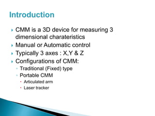
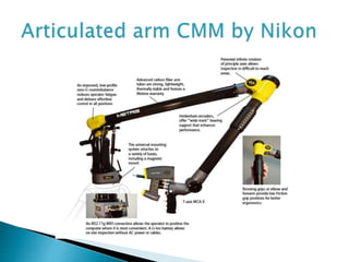
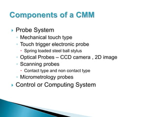
By-
Mayur Andulkar
MTech(CAD CAM)
 CMM is a 3D device for measuring 3
dimensional charateristics
 Manual or Automatic control
 Typically 3 axes : X,Y & Z
 Configurations of CMM:
◦ Traditional (Fixed) type
◦ Portable CMM
 Articulated arm
 Laser tracker
 3 main components:
◦ Body/ Structure
◦ Probe system
◦ Controller and software
 Structure:
◦ Fixed: Gantry, Cantilever or bridge type
◦ Structure mounted on air bearings
◦ Errors in structure
◦ Structure material: Granite, Ceramic, etc
◦ Temperature sensors: Invar material
 Probe System
◦ Mechanical touch type
◦ Touch trigger electronic probe
 Spring loaded steel ball stylus
◦ Optical Probes – CCD camera , 2D image
◦ Scanning probes
 Contact type and non contact type
◦ Micrometrology probes
 Control or Computing System
 The structure of CMM has remained the same
 New technology developments in:
◦ Probe system
 Non Contact type
◦ Software and controllers
 Faster computing
◦ Industrial Requirements
 CMM on shopfloor
 Multi Sensor Measuring
◦ Incorporates touch, optical or laser sensors
◦ Operator can choose which sensor to use
◦ All work done in single setup
◦ Faster
◦ The co ordinates might not be correct owing to inputs
from many sensors
 5 Axis CMM
◦ Revolutionary technology by Renishaw
◦ 2 axes controlled by servo
◦ Faster and quicker
◦ Not supported by OEM’s
 3 D Scanner
◦ Many technologies are used
◦ Color as well as contour information collected
◦ Technology
 Contact type (eg. CMM)
 May damage the object
 Relatively slow
 Non Contact type
 Active (Emit radiations eg. X ray, UV,Infrared etc)
 Passive (Take the radiations emitted naturally)
 CMM Retrofitting
◦ Much Less costly
◦ Frame is not damaged much
◦ Software changes can be easily incorporated
◦ Better accuracy and precision by using
advanced probe systems
 CAD based Inspection
 Dimensional measurement
 Profile measurement
 Angularity or orientation measurement
 Shaft measurement
 Reverse Engineering
Thank You

Cmm ppt

  • 1.
  • 2.
     CMM isa 3D device for measuring 3 dimensional charateristics  Manual or Automatic control  Typically 3 axes : X,Y & Z  Configurations of CMM: ◦ Traditional (Fixed) type ◦ Portable CMM  Articulated arm  Laser tracker
  • 4.
     3 maincomponents: ◦ Body/ Structure ◦ Probe system ◦ Controller and software  Structure: ◦ Fixed: Gantry, Cantilever or bridge type ◦ Structure mounted on air bearings ◦ Errors in structure ◦ Structure material: Granite, Ceramic, etc ◦ Temperature sensors: Invar material
  • 5.
     Probe System ◦Mechanical touch type ◦ Touch trigger electronic probe  Spring loaded steel ball stylus ◦ Optical Probes – CCD camera , 2D image ◦ Scanning probes  Contact type and non contact type ◦ Micrometrology probes  Control or Computing System
  • 7.
     The structureof CMM has remained the same  New technology developments in: ◦ Probe system  Non Contact type ◦ Software and controllers  Faster computing ◦ Industrial Requirements  CMM on shopfloor
  • 8.
     Multi SensorMeasuring ◦ Incorporates touch, optical or laser sensors ◦ Operator can choose which sensor to use ◦ All work done in single setup ◦ Faster ◦ The co ordinates might not be correct owing to inputs from many sensors  5 Axis CMM ◦ Revolutionary technology by Renishaw ◦ 2 axes controlled by servo ◦ Faster and quicker ◦ Not supported by OEM’s
  • 10.
     3 DScanner ◦ Many technologies are used ◦ Color as well as contour information collected ◦ Technology  Contact type (eg. CMM)  May damage the object  Relatively slow  Non Contact type  Active (Emit radiations eg. X ray, UV,Infrared etc)  Passive (Take the radiations emitted naturally)
  • 11.
     CMM Retrofitting ◦Much Less costly ◦ Frame is not damaged much ◦ Software changes can be easily incorporated ◦ Better accuracy and precision by using advanced probe systems
  • 12.
     CAD basedInspection  Dimensional measurement  Profile measurement  Angularity or orientation measurement  Shaft measurement  Reverse Engineering
  • 13.

Editor's Notes