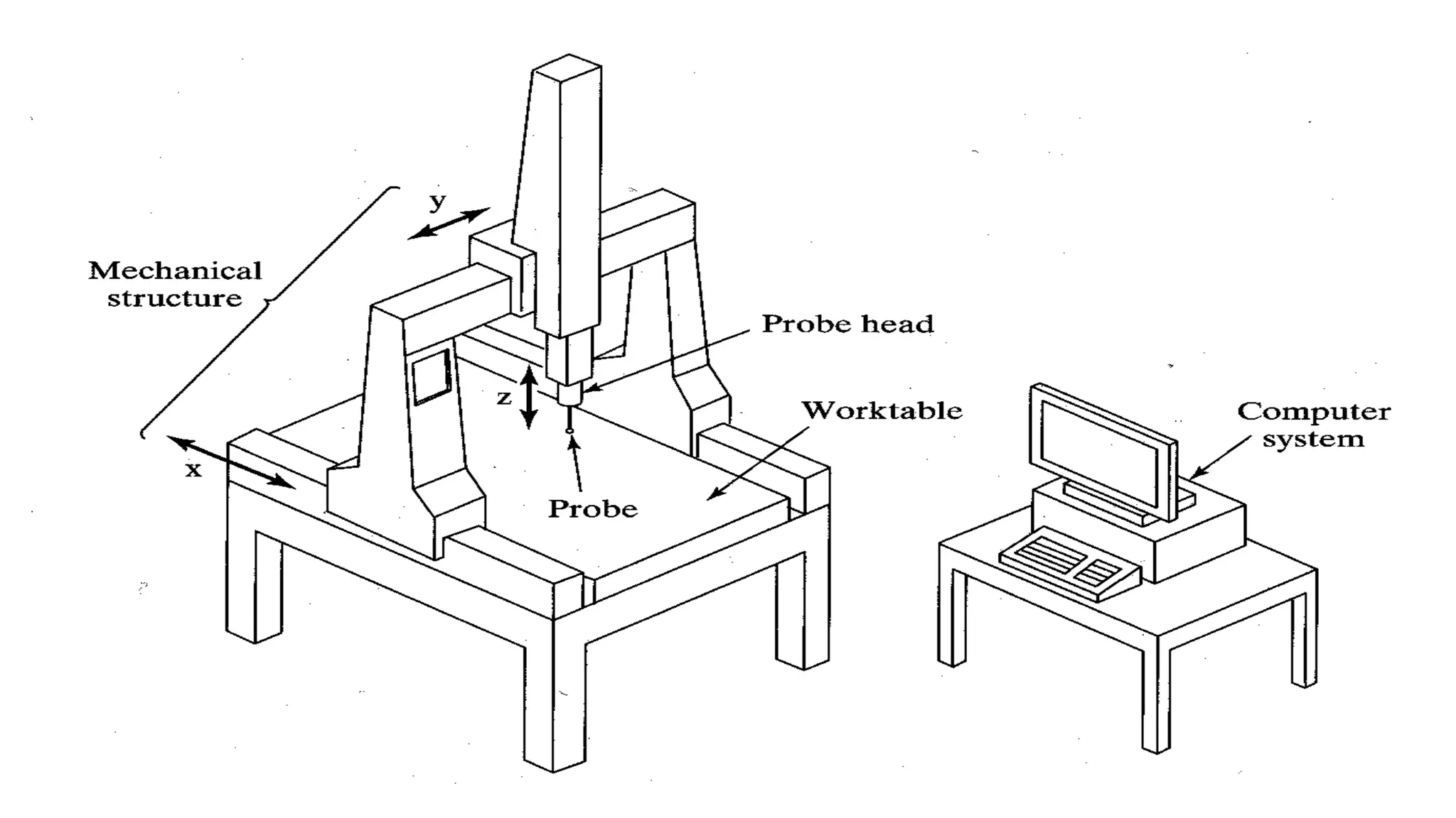
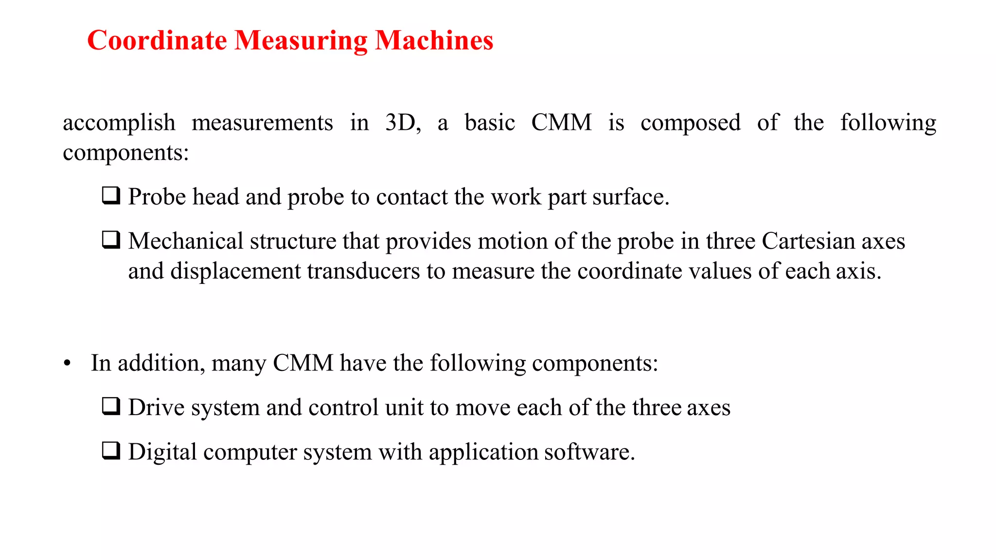
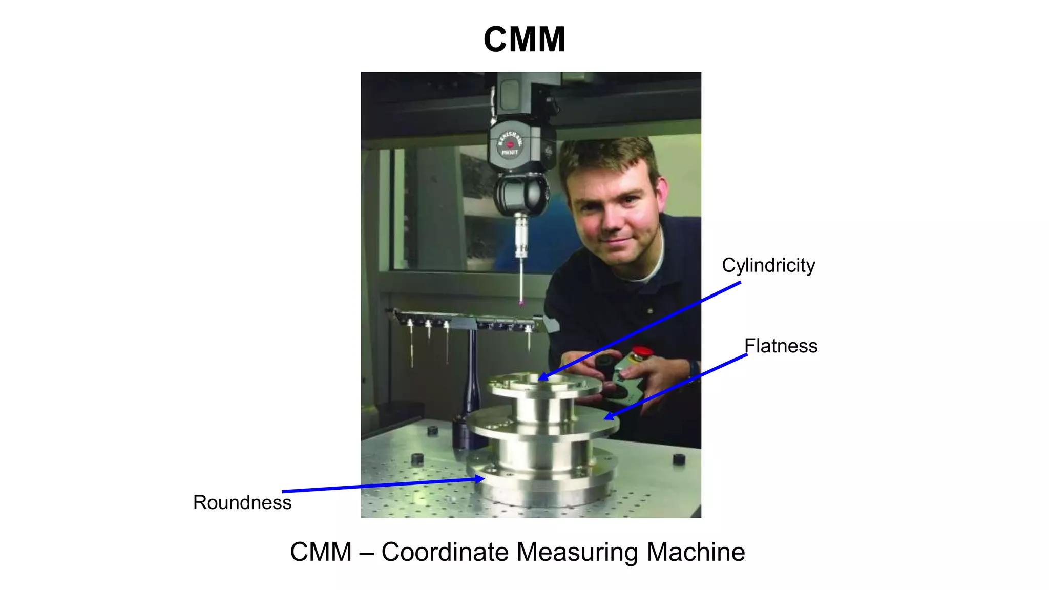
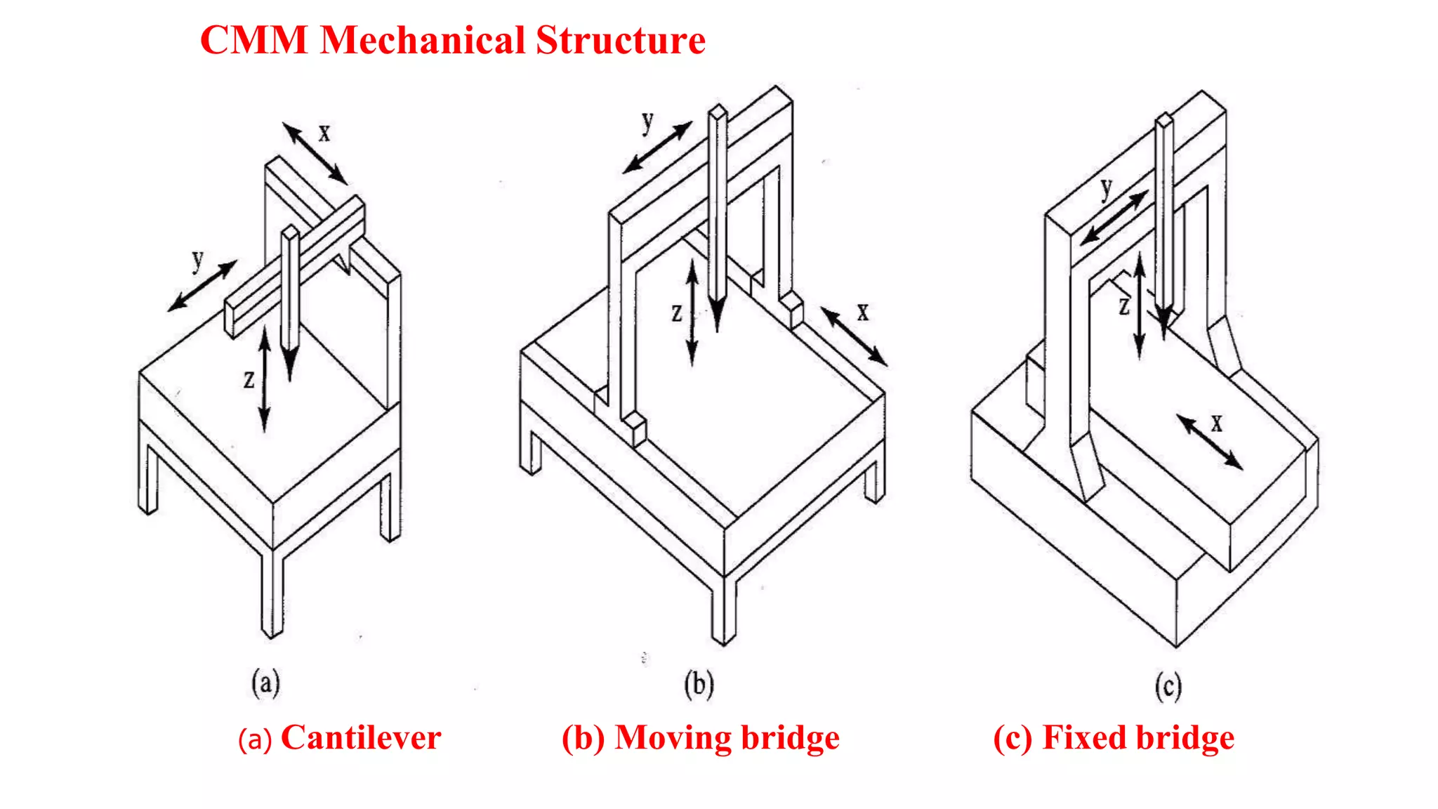
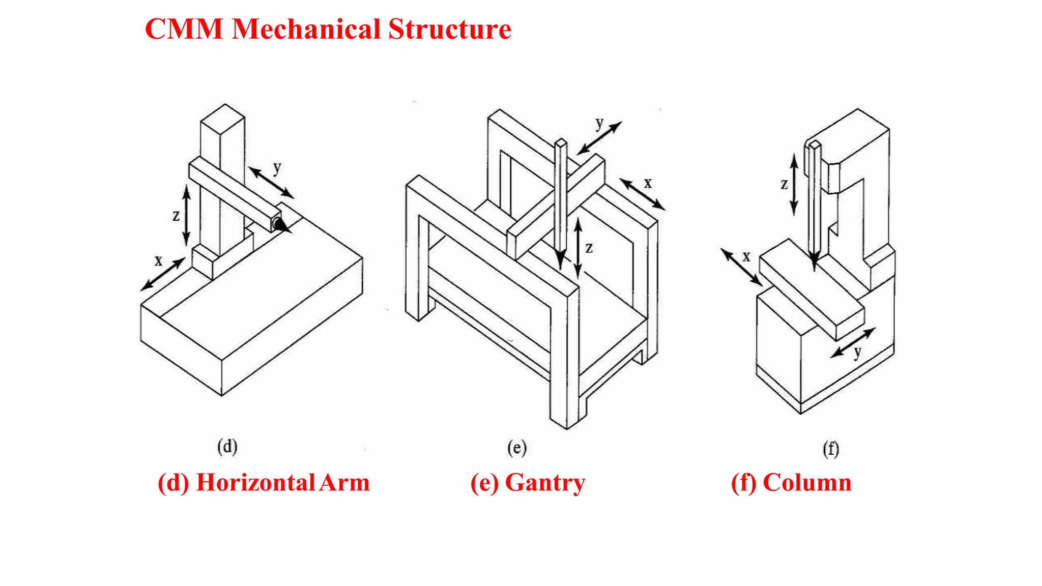
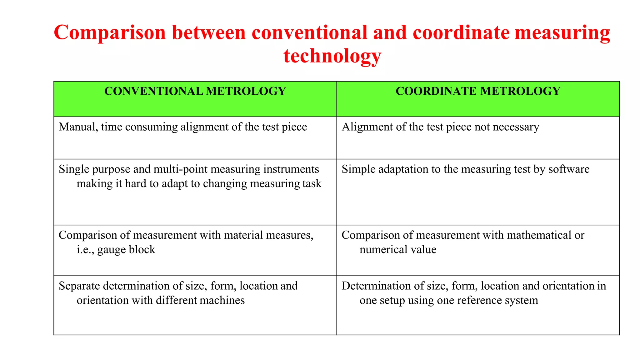
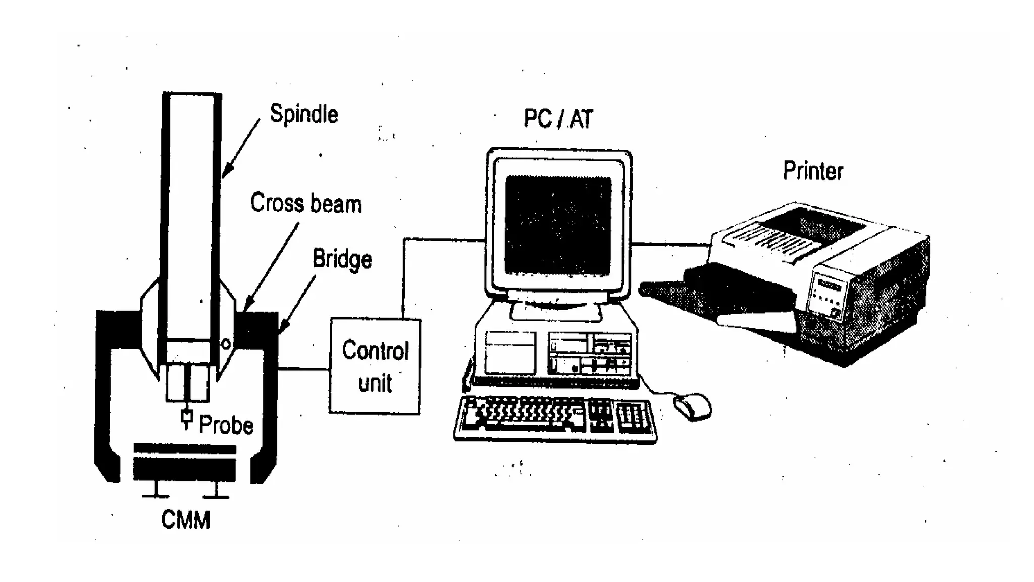
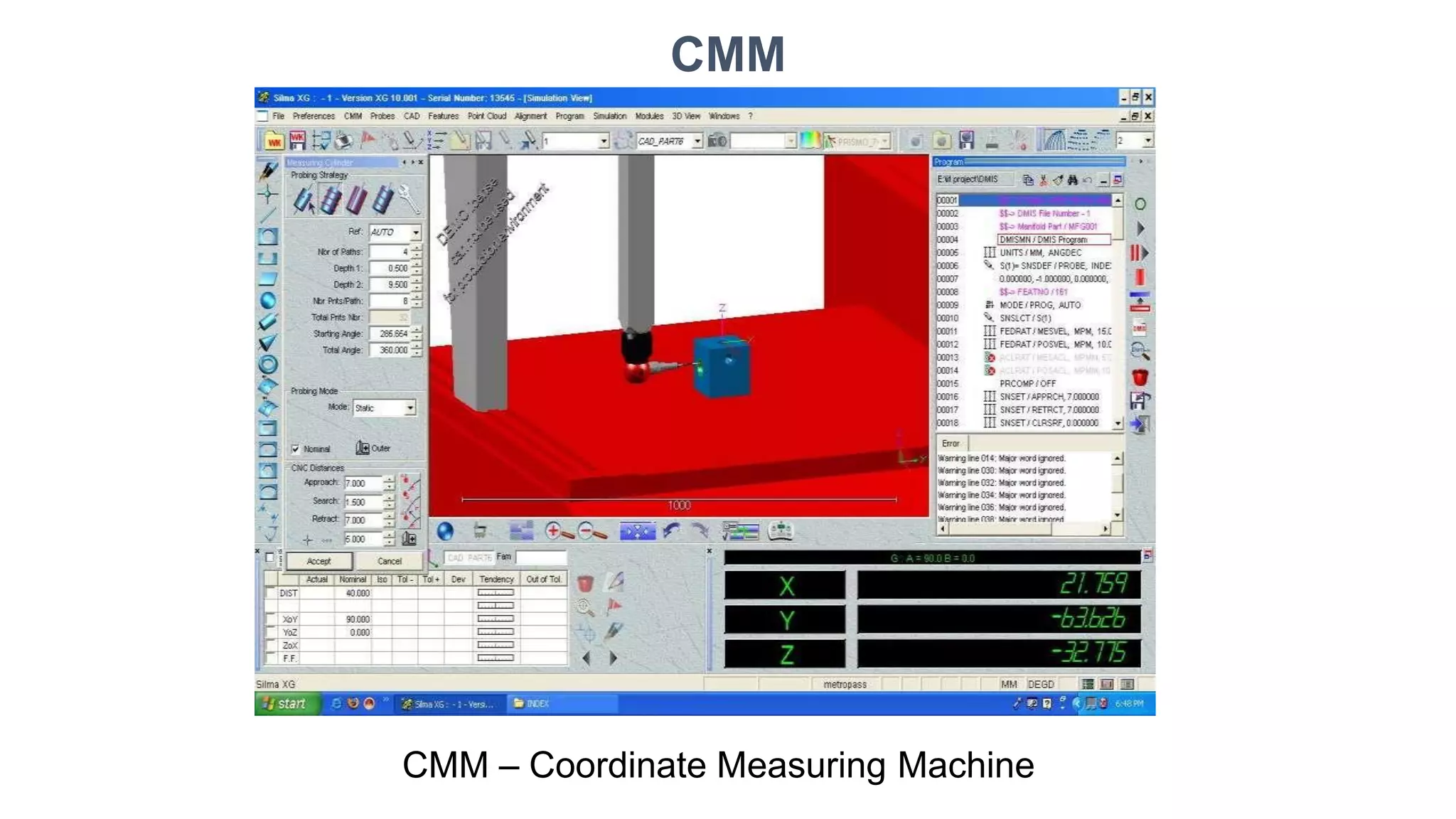
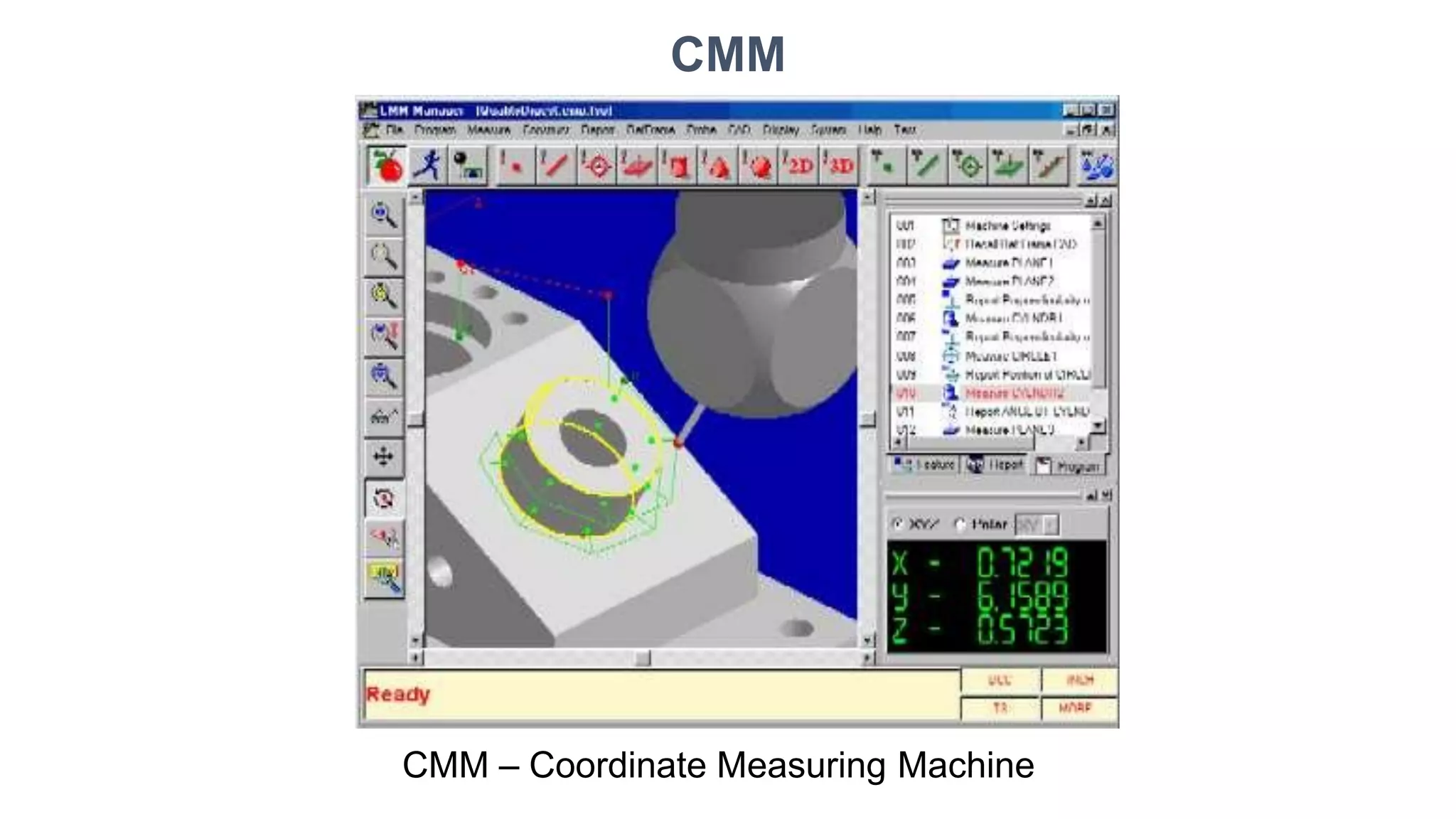
METROLOGY AND QUQLITY CONTROL
(Course Code:302025)
Prof. (Dr.)D. M. Mate
(Associate Professor)
JSPMs,
Rajarshi Shahu College of Engineering, Tathawade, Pune-33
(An Autonomous Institution Affiliated to Savitribai Phule Pune University
Coordinate Measuring Machine
(CMM)
TYPES OF MEASURING MACHINES
1. Length bar measuring machine.
2. Newall measuring machine.
3. Universal measuring machine.
4. Co-ordinate measuring machine.
5. Computer controlled co-ordinate measuring machine.
Coordinate Measuring Machines
• Coordinate metrology is concerned with the measurement
of the actual shape and dimensions of an object and
comparing these with the desired shape and dimensions.
• In this connection, coordinate metrology consists of the
evaluation of the location, orientation, dimensions, and
geometry of the part or object.
• A Coordinate Measuring Machine (CMM) is an
electromechanical system designed to perform coordinate
metrology.
Coordinate Measuring Machine (CMM)
➢Measuring machine consisting of a contact probe and a mechanism to position
the probe in three-dimensions relative to surfaces and features of a work part
➢The probe is fastened to a structure that allows movement relative to the part
➢Part is fixture on worktable connected to structure
➢The location coordinates of the probe can be accurately recorded as it contacts
the part surface to obtain part geometry data
Coordinate Measuring Machines
• A CMM consists of a constant probe that can be positioned in 3D space
relative to the surface of a work part, and the x, y, and z coordinates of the
probe can be accurately and precisely recorded to obtain dimensional data
concerning the part geometry
accomplish measurements in 3D, a basic CMM is composed of the following
components:
❑ Probe head and probe to contact the work part surface.
❑ Mechanical structure that provides motion of the probe in three Cartesian axes
and displacement transducers to measure the coordinate values of each axis.
• In addition, many CMM have the following components:
❑ Drive system and control unit to move each of the three axes
❑ Digital computer system with application software.
Coordinate Measuring Machines
CMM
Roundness
CMM – Coordinate Measuring Machine
Cylindricity
Flatness
CMM Mechanical Structure
(a) Cantilever (b) Moving bridge (c) Fixed bridge
CMM Mechanical Structure
(d) HorizontalArm (e) Gantry (f) Column
Cantilever type
• A vertical probe moves in the z-axis
• Carried by a cantilevered arm that moves in the y-axis
• This arm also moves laterally through the x-axis
• Advantage- a fixed table allows good accessibility to the
work piece
• Disadvantage- the bending caused by the cantilever design
• The cantilever design offers a long table with relatively
small measuring ranges in the other two axis.
• Suitable for measuring long, thin part
Moving bridge type
• Most widely used
• Has stationary table to support work piece to be
measured and a moving bridge
• Disadvantage- with this design, the phenomenon of
yawing (sometimes called walking) can occur- affect
the accuracy
• Advantage- reduce bending effect
Fixed bridge type
• In the fixed bridge configuration, the bridge is
rigidly attached to the machine bed
• This design eliminates the phenomenon of
walking and provides high rigidity
Column type
• Often referred to as universal measuring
machine instead of CMM
• The column type CMM construction provides
exceptional rigidity and accuracy
• These machines are usually reserved for gauge
rooms rather than inspection
Horizontal arm type
• Unlike the previous machines, the basic horizontal
arm-type CMM
• Also referred to as layout machine
• Has a moving arm, and the probe is carried along the
y-axis
• Advantage- provides a large area, unobstructed work
area
• Ideal configuration for measurement of automobile
parts
Gantry type
• The support of work piece is independent of the x and y axes,
both are overhead, supported by four vertical columns rising
from the floor
• This setup allows you to walk along the work piece with the
probe, which is helpful for extremely large pieces
CMM Operation and Programming
• Positioning the probe relative to the part can be accomplished in several ways, ranging from
manual operation to direct computer control.
• Computer-controlled CMMs operate much like CNC machine tools, and these machines must
be programmed.
CMM Controls
• The methods of operating and controlling a CMM can be classified into four main
categories:
1. Manual drive,
2. Manual drive with computer-assisted data processing,
3. Motor drive with computer-assisted data processing, and
4. Direct Computer Control with computer-assisted data processing.
CMM Controls
• In manual drive CMM, the human operator physically move the probe along the
machine’s axes to make contact with the part and record the measurements.
• The measurements are provided by a digital readout, which the operator can
record either manually or with paper print out.
• Any calculations on the data must be made by the operator.
• A CMM with manual drive and computer-assisted data processing provides some data
processing and computational capability for performing the calculations required to
evaluate a give part feature.
• The types of data processing and computations range from simple conversioons between
units to more complicated geometry calculations, such as determining the angle between
two planes.
CMM Controls
• A motor-driven CMM with computer-assisted data processing uses electric motors
to drive the probe along the machine axes under operatorcontrol.
• A joystick or similar device is used as the means of controlling themotion.
• Motor-driven CMMs are generally equipped with data processing to accomplish
the geometric computations required in feature assessment.
• A CMM with direct computer control (DCC) operates like a CNC machine tool. It
is motorized and the movements of the coordinate axes are controlled by a
dedicated computer under program control.
• The computer also performs the various data processing and calculation functions.
• As with a CNC machine tool, the DCC CMM requires part programming.
DCC CMM Programming
• There are twp principle methods of programming a DCC measuring machine:
1. Manual leadthrough method.
2. Off-line programming.
• In the Manual Lead through method, the operator leads the CMM probe through the various
motions required in the inspection sequence, indicating the points and surfaces that are to be
measured and recording these into the control memory.
• During regular operation, the CMM controller plays back the program to execute the inspection
procedure.
• Off-line Programming is accomplished in the manner of computer-assisted NC part
programming, The program is prepared off-line based on the part drawing and then
downloaded to the CMM controller for execution.
TYPES OF PROBES
• Two general categories
1. Contact (see figure)
• Touch-trigger probe
• Analog scanning probe
2. Noncontact
For inspection of printed circuit board, measuring a clay
of wax model, when the object being measured would
be deformed by the for of stylus
• laser probes
• video probes
Contact probes
1. Touch trigger probe
• As the sensor makes contact with the part, the difference in contact resistance indicatesthat
the probe has been deflected
• The computer records this contact point coordinate space
• An LED light and an audible signal usually indicate contact
• Touch probe assemblies consist of three components; probe head, probe andstylus
2. Analog scanning probe
• Use to measure contour surfaces, complex, irregular
• Remains in contact with the surface of the part as it moves
• Improve the speed and accuracy
Non-contact probe
1. Laser scanning probe
• Laser probes project a light beam onto the surface of apart
• When the light beam is triggered, the position of beam is read by triangulationthrough
a lens in the probe receptor
• Laser tool have a high degree of speed and accuracy
2. Video probe
• The feature are measured by computer ‘count’of the pixels of the electronic image
• The camera is capable of generating multitude of measurements points within a single
video frame
Trigger type probe system
Measuring type probe system
Probe head, probes and stylus
Multiple shapes of sylus
CALIBRATION OF THREE CO-ORDINATE MEASURING MACHINE
APPLICATIONS
1) Co-ordinate measuring machines find applications in automobile, machine tool,
electronics, space and many other large companies.
2) These machines are best suited for the test and inspection of test equipment, gauges
and tools.
3)For aircraft and space vehicles, hundred percent inspections is carried out by using
CMM.
4) CMM can be used for determining dimensional accuracy of the components.
5)These are ideal for determination of shape and position, maximum metal condition,
linkage of results etc. which cannot do in conventional machines.
6) CMM can also be used for sorting tasks to achieve optimum pairing of components
within tolerance limits.
7)CMMs are also best for ensuring economic viability of NC machines by reducing
their
downtime for inspection results. They also help in reducing cost, rework cost at the
appropriate time with a suitable CMM.
ADVANTAGES
• The inspection rate is increased.
• Accuracy is more.
• Operators error can be minimized.
• Skill requirements of the operator is reduced.
• Reduced inspection fix Turing and maintenancecost.
• Reduction in calculating and recording time.
• Reduction in set up time.
• No need of separate go / no go gauges for each feature.
• Reduction of scrap and good part rejection.
• Reduction in off line analysis time.
DISADVANTAGES
• The table and probe may not be in perfect alignment.
• The probe may have run out.
• The probe moving in Z-axis may have some perpendicular errors.
• Probe while moving in X and Y direction may not be square to each
other.
• There may be errors in digital system.
CAUSES OF ERRORS IN CMM
• The table and probes are in imperfect alignment. The probes may have a degree of
run out and move up and down in the Z-axis may occur perpendicularity errors. So
CMM should be calibrated with master plates before using the machine.
• Dimensional errors of a CMM is influenced by
Straightness and perpendicularity of the guide ways.
Scale division and adjustment.
Probe length.
Probe system calibration, repeatability, zero point setting and reversal error.
Error due to digitization.
Environment
• Other errors can be controlled by the manufacture and minimized by the
measuring software. The length of the probe should be minimum to reduce
deflection.
• The weight of the work piece may change the geometry of the guide ways and
therefore, the work piece must not exceed maximum weight.
• Variation in temperature of CMM, specimen and measuring lab influence the
uncertainly of measurements.
• Translation errors occur from error in the scale division and error in straightness
perpendicular to the corresponding axis direction.
• Perpendicularity error occurs if three axes are not orthogonal.
Comparison between conventional and coordinate measuring
technology
CONVENTIONAL METROLOGY COORDINATE METROLOGY
Manual, time consuming alignment of the test piece Alignment of the test piece not necessary
Single purpose and multi-point measuring instruments
making it hard to adapt to changing measuring task
Simple adaptation to the measuring test by software
Comparison of measurement with material measures,
i.e., gauge block
Comparison of measurement with mathematical or
numerical value
Separate determination of size, form, location and
orientation with different machines
Determination of size, form, location and orientation in
one setup using one reference system
Features of CMM Software
• Measurement of diameter, center distance, length.
• Measurement of plane and spatial carvers.
• Minimum CNC programmed.
• Data communications.
• Digital input and output command.
•Program me for the measurement of spur, helical, bevel’ and hypoid
gears.
• Interface to CAD software
• Generally software packages contains some or all of the following capabilities:
1. Resolution selection
2. Conversion between SI and English (mm and inch)
3. Conversion of rectangular coordinates to polar coordinates
4. Axis scaling
5. Datum selection and reset
6. Circle center and diameter solution
7. Bolt-circle center and diameter
8. Save and recall previous datum
9. Nominal and tolerance entry
10. Out-of tolerance computation
CMM
CMM – Coordinate Measuring Machine
CMM
CMM – Coordinate Measuring Machine
$$* IIT Delhi- DMIS File For Verifying Cyolninicditryic:ity:
Generated by Bhaskar
$$-> DMIS File Number - 12
$$-> Manifold Part / MFG0012
DMISMN / DMIS Program
UNITS / MM, ANGDEC
$$$$-->>FFEEAATTNNOO//81828
$$ Verify Gtol g012
T(COLNIINCDITRYI)C=ITTYO)L=/TOCNLC/TCYY,L0C.0T0Y,500.0005000
OUTPUT / FA(M_CN10)2,)T,AT(AC(YCLOINIDCRITICYI)TY)
$$-> END /
EENNDDFFIILL
DMIS
$$* IIT Delhi- DMIS File For Measuring ACoylnine:dGere:nGeeranteerdatbeydBbhyaBskharskar
$$$$-->>DDMMIISSFFiilleeNNuummbbeerr--21
$$-> Manifold Part /MFG0021
DMISMN / DMIS Program
UNITS / MM, ANGDEC
0S(.010)=00S0N0S,D0E.0F0/00P0R0O,B1E.0,0I0N0D0E0X,, 1P0O0L.0,000.000,020.0,000.00000, $
$0$.0-0>0F0E0A0T,N0.O00/080800,1.000000, 100.000000, 4.000000 M$$O-
>DFEE/APTRNOOG/, 1A2U8TO
SMNOSDLECT//PRS(O2G), AUTO FSNEDSLRCATT//SM(1E)SVEL,
MPM, 15.000000 FEDRAT / PMOESSVVEELL,,
MMPPMM,,2105..000000000000AFECDLRAT/ MPOESSVAECLL,,
MPMM2,05..000000000000ACLRAT / PMOESSAACCLL,,
MMPPMMMM,,150.0.00000000000PARCLCROAMTP//POOFSFACL,
MPMM, 10.000000
SPNRSCEOTM/PA/POPFRFCH, 0.249996
SNSET / RAPEPTRCHT, 05.254090909060
SNSET / CRLERTSRRCFT,,05..050000000000
FSN(MSE_CTN/0C2L)=RSFREFA,T0./0C0O00N0E0,INNER, CART, $
0F(.0M0_0C0Y0001,)0=.0F0E0A0T00/,C-Y4L4N.9D9R99,8IN1,N$ER,CART, $
0.000000, 0.000000, 10.000000, 3$6.870000
M0.0E0A0S0/0C0O,0N.0E0,0F0(M00_,C-N10.020)0,060.00,03000.0000000
RF(ABPNID_/210.)0=0F0E0A0T0/ PLANE, CART, $
G0.O0T0O00/000.,000.000000,000.,000.0000,00$0000,2.000000
R0.A0P0I0D00/01,.00.0000000000,1.000000,
GF(OBTNOD/_201.0)0=0F0E0A0T,0/.0P0L0A0N0E0,,C2A.0R0T0,0$00
R0.A0P0I0D00/01,.00.0000000000,-10.000000, $
G0.O0T0O00/000.,000.000000000,00.,0-010.0000000,0-307,.000000
PBTOMUNEADS//FC(MAR_CTY,16).,00F0(B0N08D,_02.00)0,0F0(0B0N,D-3_72.10)00000,$
-M0E.7A9S9/99C9Y,L0N.0D0R0,0F0(0M,0_C.6Y010)0,0312
P...T...M....E...A...S.../....C...ART,0.000000, 6.000008, -37.000000, $
0G.O0T0O00/000.,0-000.7090909,909.0,0.6000000,0-21.000000
PTMEAS / CART, -103.0.00000000000,,-06.000008, -23.70.00000,0$,$
01.000000,0.709090909090,0.60000010
PTMEAS / CART, 9.192388, 9.192388, -2.000000, $
0.707107, 0.707107, 0.000000
DMIS
MACHINE VISION
VISION SYSTEM
VISION SYSTEM
Principle:
FUNCTION OF MACHINE VISION
INTEGRATION OF CAD/CAM WITH INSPECTION SYSTEM
FLEXIBLE INSPECTION SYSTEM

Coordinate Measuring Machine (CMM)

  • 1.
    METROLOGY AND QUQLITYCONTROL (Course Code:302025) Prof. (Dr.)D. M. Mate (Associate Professor) JSPMs, Rajarshi Shahu College of Engineering, Tathawade, Pune-33 (An Autonomous Institution Affiliated to Savitribai Phule Pune University Coordinate Measuring Machine (CMM)
  • 2.
    TYPES OF MEASURINGMACHINES 1. Length bar measuring machine. 2. Newall measuring machine. 3. Universal measuring machine. 4. Co-ordinate measuring machine. 5. Computer controlled co-ordinate measuring machine.
  • 3.
    Coordinate Measuring Machines •Coordinate metrology is concerned with the measurement of the actual shape and dimensions of an object and comparing these with the desired shape and dimensions. • In this connection, coordinate metrology consists of the evaluation of the location, orientation, dimensions, and geometry of the part or object. • A Coordinate Measuring Machine (CMM) is an electromechanical system designed to perform coordinate metrology.
  • 4.
    Coordinate Measuring Machine(CMM) ➢Measuring machine consisting of a contact probe and a mechanism to position the probe in three-dimensions relative to surfaces and features of a work part ➢The probe is fastened to a structure that allows movement relative to the part ➢Part is fixture on worktable connected to structure ➢The location coordinates of the probe can be accurately recorded as it contacts the part surface to obtain part geometry data
  • 5.
    Coordinate Measuring Machines •A CMM consists of a constant probe that can be positioned in 3D space relative to the surface of a work part, and the x, y, and z coordinates of the probe can be accurately and precisely recorded to obtain dimensional data concerning the part geometry
  • 7.
    accomplish measurements in3D, a basic CMM is composed of the following components: ❑ Probe head and probe to contact the work part surface. ❑ Mechanical structure that provides motion of the probe in three Cartesian axes and displacement transducers to measure the coordinate values of each axis. • In addition, many CMM have the following components: ❑ Drive system and control unit to move each of the three axes ❑ Digital computer system with application software. Coordinate Measuring Machines
  • 9.
    CMM Roundness CMM – CoordinateMeasuring Machine Cylindricity Flatness
  • 10.
    CMM Mechanical Structure (a)Cantilever (b) Moving bridge (c) Fixed bridge
  • 11.
    CMM Mechanical Structure (d)HorizontalArm (e) Gantry (f) Column
  • 12.
    Cantilever type • Avertical probe moves in the z-axis • Carried by a cantilevered arm that moves in the y-axis • This arm also moves laterally through the x-axis • Advantage- a fixed table allows good accessibility to the work piece • Disadvantage- the bending caused by the cantilever design • The cantilever design offers a long table with relatively small measuring ranges in the other two axis. • Suitable for measuring long, thin part
  • 13.
    Moving bridge type •Most widely used • Has stationary table to support work piece to be measured and a moving bridge • Disadvantage- with this design, the phenomenon of yawing (sometimes called walking) can occur- affect the accuracy • Advantage- reduce bending effect
  • 14.
    Fixed bridge type •In the fixed bridge configuration, the bridge is rigidly attached to the machine bed • This design eliminates the phenomenon of walking and provides high rigidity
  • 15.
    Column type • Oftenreferred to as universal measuring machine instead of CMM • The column type CMM construction provides exceptional rigidity and accuracy • These machines are usually reserved for gauge rooms rather than inspection
  • 16.
    Horizontal arm type •Unlike the previous machines, the basic horizontal arm-type CMM • Also referred to as layout machine • Has a moving arm, and the probe is carried along the y-axis • Advantage- provides a large area, unobstructed work area • Ideal configuration for measurement of automobile parts
  • 17.
    Gantry type • Thesupport of work piece is independent of the x and y axes, both are overhead, supported by four vertical columns rising from the floor • This setup allows you to walk along the work piece with the probe, which is helpful for extremely large pieces
  • 18.
    CMM Operation andProgramming • Positioning the probe relative to the part can be accomplished in several ways, ranging from manual operation to direct computer control. • Computer-controlled CMMs operate much like CNC machine tools, and these machines must be programmed. CMM Controls • The methods of operating and controlling a CMM can be classified into four main categories: 1. Manual drive, 2. Manual drive with computer-assisted data processing, 3. Motor drive with computer-assisted data processing, and 4. Direct Computer Control with computer-assisted data processing.
  • 19.
    CMM Controls • Inmanual drive CMM, the human operator physically move the probe along the machine’s axes to make contact with the part and record the measurements. • The measurements are provided by a digital readout, which the operator can record either manually or with paper print out. • Any calculations on the data must be made by the operator. • A CMM with manual drive and computer-assisted data processing provides some data processing and computational capability for performing the calculations required to evaluate a give part feature. • The types of data processing and computations range from simple conversioons between units to more complicated geometry calculations, such as determining the angle between two planes.
  • 20.
    CMM Controls • Amotor-driven CMM with computer-assisted data processing uses electric motors to drive the probe along the machine axes under operatorcontrol. • A joystick or similar device is used as the means of controlling themotion. • Motor-driven CMMs are generally equipped with data processing to accomplish the geometric computations required in feature assessment. • A CMM with direct computer control (DCC) operates like a CNC machine tool. It is motorized and the movements of the coordinate axes are controlled by a dedicated computer under program control. • The computer also performs the various data processing and calculation functions. • As with a CNC machine tool, the DCC CMM requires part programming.
  • 21.
    DCC CMM Programming •There are twp principle methods of programming a DCC measuring machine: 1. Manual leadthrough method. 2. Off-line programming. • In the Manual Lead through method, the operator leads the CMM probe through the various motions required in the inspection sequence, indicating the points and surfaces that are to be measured and recording these into the control memory. • During regular operation, the CMM controller plays back the program to execute the inspection procedure. • Off-line Programming is accomplished in the manner of computer-assisted NC part programming, The program is prepared off-line based on the part drawing and then downloaded to the CMM controller for execution.
  • 22.
    TYPES OF PROBES •Two general categories 1. Contact (see figure) • Touch-trigger probe • Analog scanning probe 2. Noncontact For inspection of printed circuit board, measuring a clay of wax model, when the object being measured would be deformed by the for of stylus • laser probes • video probes
  • 23.
    Contact probes 1. Touchtrigger probe • As the sensor makes contact with the part, the difference in contact resistance indicatesthat the probe has been deflected • The computer records this contact point coordinate space • An LED light and an audible signal usually indicate contact • Touch probe assemblies consist of three components; probe head, probe andstylus 2. Analog scanning probe • Use to measure contour surfaces, complex, irregular • Remains in contact with the surface of the part as it moves • Improve the speed and accuracy
  • 24.
    Non-contact probe 1. Laserscanning probe • Laser probes project a light beam onto the surface of apart • When the light beam is triggered, the position of beam is read by triangulationthrough a lens in the probe receptor • Laser tool have a high degree of speed and accuracy 2. Video probe • The feature are measured by computer ‘count’of the pixels of the electronic image • The camera is capable of generating multitude of measurements points within a single video frame
  • 25.
  • 26.
  • 27.
  • 28.
  • 29.
    CALIBRATION OF THREECO-ORDINATE MEASURING MACHINE
  • 30.
    APPLICATIONS 1) Co-ordinate measuringmachines find applications in automobile, machine tool, electronics, space and many other large companies. 2) These machines are best suited for the test and inspection of test equipment, gauges and tools. 3)For aircraft and space vehicles, hundred percent inspections is carried out by using CMM. 4) CMM can be used for determining dimensional accuracy of the components. 5)These are ideal for determination of shape and position, maximum metal condition, linkage of results etc. which cannot do in conventional machines.
  • 31.
    6) CMM canalso be used for sorting tasks to achieve optimum pairing of components within tolerance limits. 7)CMMs are also best for ensuring economic viability of NC machines by reducing their downtime for inspection results. They also help in reducing cost, rework cost at the appropriate time with a suitable CMM.
  • 32.
    ADVANTAGES • The inspectionrate is increased. • Accuracy is more. • Operators error can be minimized. • Skill requirements of the operator is reduced. • Reduced inspection fix Turing and maintenancecost. • Reduction in calculating and recording time. • Reduction in set up time. • No need of separate go / no go gauges for each feature. • Reduction of scrap and good part rejection. • Reduction in off line analysis time.
  • 33.
    DISADVANTAGES • The tableand probe may not be in perfect alignment. • The probe may have run out. • The probe moving in Z-axis may have some perpendicular errors. • Probe while moving in X and Y direction may not be square to each other. • There may be errors in digital system.
  • 34.
    CAUSES OF ERRORSIN CMM • The table and probes are in imperfect alignment. The probes may have a degree of run out and move up and down in the Z-axis may occur perpendicularity errors. So CMM should be calibrated with master plates before using the machine. • Dimensional errors of a CMM is influenced by Straightness and perpendicularity of the guide ways. Scale division and adjustment. Probe length. Probe system calibration, repeatability, zero point setting and reversal error. Error due to digitization. Environment
  • 35.
    • Other errorscan be controlled by the manufacture and minimized by the measuring software. The length of the probe should be minimum to reduce deflection. • The weight of the work piece may change the geometry of the guide ways and therefore, the work piece must not exceed maximum weight. • Variation in temperature of CMM, specimen and measuring lab influence the uncertainly of measurements. • Translation errors occur from error in the scale division and error in straightness perpendicular to the corresponding axis direction. • Perpendicularity error occurs if three axes are not orthogonal.
  • 36.
    Comparison between conventionaland coordinate measuring technology CONVENTIONAL METROLOGY COORDINATE METROLOGY Manual, time consuming alignment of the test piece Alignment of the test piece not necessary Single purpose and multi-point measuring instruments making it hard to adapt to changing measuring task Simple adaptation to the measuring test by software Comparison of measurement with material measures, i.e., gauge block Comparison of measurement with mathematical or numerical value Separate determination of size, form, location and orientation with different machines Determination of size, form, location and orientation in one setup using one reference system
  • 38.
    Features of CMMSoftware • Measurement of diameter, center distance, length. • Measurement of plane and spatial carvers. • Minimum CNC programmed. • Data communications. • Digital input and output command. •Program me for the measurement of spur, helical, bevel’ and hypoid gears. • Interface to CAD software
  • 39.
    • Generally softwarepackages contains some or all of the following capabilities: 1. Resolution selection 2. Conversion between SI and English (mm and inch) 3. Conversion of rectangular coordinates to polar coordinates 4. Axis scaling 5. Datum selection and reset 6. Circle center and diameter solution 7. Bolt-circle center and diameter 8. Save and recall previous datum 9. Nominal and tolerance entry 10. Out-of tolerance computation
  • 40.
    CMM CMM – CoordinateMeasuring Machine
  • 41.
    CMM CMM – CoordinateMeasuring Machine
  • 42.
    $$* IIT Delhi-DMIS File For Verifying Cyolninicditryic:ity: Generated by Bhaskar $$-> DMIS File Number - 12 $$-> Manifold Part / MFG0012 DMISMN / DMIS Program UNITS / MM, ANGDEC $$$$-->>FFEEAATTNNOO//81828 $$ Verify Gtol g012 T(COLNIINCDITRYI)C=ITTYO)L=/TOCNLC/TCYY,L0C.0T0Y,500.0005000 OUTPUT / FA(M_CN10)2,)T,AT(AC(YCLOINIDCRITICYI)TY) $$-> END / EENNDDFFIILL DMIS
  • 43.
    $$* IIT Delhi-DMIS File For Measuring ACoylnine:dGere:nGeeranteerdatbeydBbhyaBskharskar $$$$-->>DDMMIISSFFiilleeNNuummbbeerr--21 $$-> Manifold Part /MFG0021 DMISMN / DMIS Program UNITS / MM, ANGDEC 0S(.010)=00S0N0S,D0E.0F0/00P0R0O,B1E.0,0I0N0D0E0X,, 1P0O0L.0,000.000,020.0,000.00000, $ $0$.0-0>0F0E0A0T,N0.O00/080800,1.000000, 100.000000, 4.000000 M$$O- >DFEE/APTRNOOG/, 1A2U8TO SMNOSDLECT//PRS(O2G), AUTO FSNEDSLRCATT//SM(1E)SVEL, MPM, 15.000000 FEDRAT / PMOESSVVEELL,, MMPPMM,,2105..000000000000AFECDLRAT/ MPOESSVAECLL,, MPMM2,05..000000000000ACLRAT / PMOESSAACCLL,, MMPPMMMM,,150.0.00000000000PARCLCROAMTP//POOFSFACL, MPMM, 10.000000 SPNRSCEOTM/PA/POPFRFCH, 0.249996 SNSET / RAPEPTRCHT, 05.254090909060 SNSET / CRLERTSRRCFT,,05..050000000000 FSN(MSE_CTN/0C2L)=RSFREFA,T0./0C0O00N0E0,INNER, CART, $ 0F(.0M0_0C0Y0001,)0=.0F0E0A0T00/,C-Y4L4N.9D9R99,8IN1,N$ER,CART, $ 0.000000, 0.000000, 10.000000, 3$6.870000 M0.0E0A0S0/0C0O,0N.0E0,0F0(M00_,C-N10.020)0,060.00,03000.0000000 RF(ABPNID_/210.)0=0F0E0A0T0/ PLANE, CART, $ G0.O0T0O00/000.,000.000000,000.,000.0000,00$0000,2.000000 R0.A0P0I0D00/01,.00.0000000000,1.000000, GF(OBTNOD/_201.0)0=0F0E0A0T,0/.0P0L0A0N0E0,,C2A.0R0T0,0$00 R0.A0P0I0D00/01,.00.0000000000,-10.000000, $ G0.O0T0O00/000.,000.000000000,00.,0-010.0000000,0-307,.000000 PBTOMUNEADS//FC(MAR_CTY,16).,00F0(B0N08D,_02.00)0,0F0(0B0N,D-3_72.10)00000,$ -M0E.7A9S9/99C9Y,L0N.0D0R0,0F0(0M,0_C.6Y010)0,0312 P...T...M....E...A...S.../....C...ART,0.000000, 6.000008, -37.000000, $ 0G.O0T0O00/000.,0-000.7090909,909.0,0.6000000,0-21.000000 PTMEAS / CART, -103.0.00000000000,,-06.000008, -23.70.00000,0$,$ 01.000000,0.709090909090,0.60000010 PTMEAS / CART, 9.192388, 9.192388, -2.000000, $ 0.707107, 0.707107, 0.000000 DMIS
  • 44.
  • 45.
  • 46.
  • 48.
  • 49.
    INTEGRATION OF CAD/CAMWITH INSPECTION SYSTEM
  • 50.