Download as PDF, PPTX

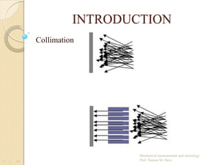
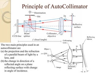
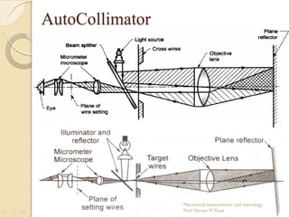
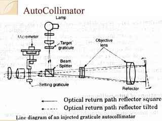
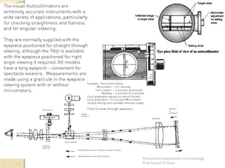
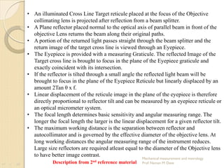
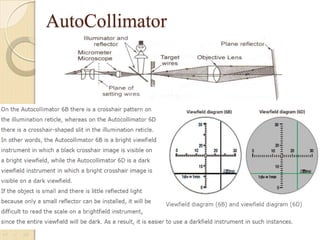

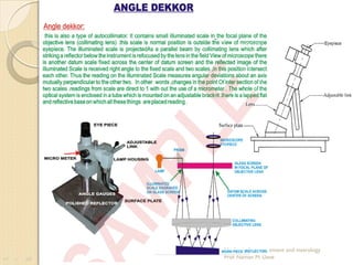
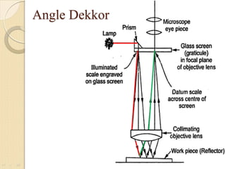
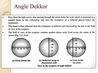
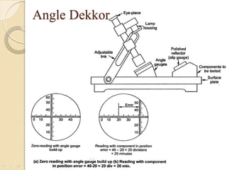
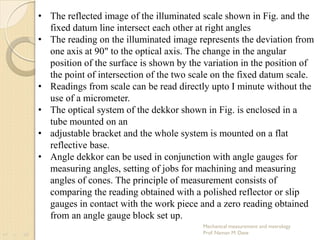
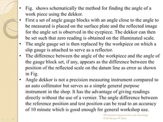

The document discusses the principles and applications of autocollimators and angle dekkors in mechanical measurement and metrology. It details how autocollimators use light reflection for precise angle measurements, with applications such as checking surface flatness, while angle dekkors provide a simpler means to measure angles in workshop settings. Both instruments have specific requirements for optimal performance, including the need for highly polished surfaces and effects of air currents on accuracy.


