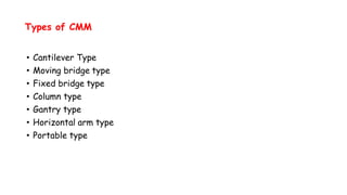
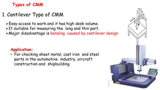
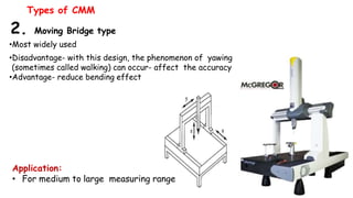
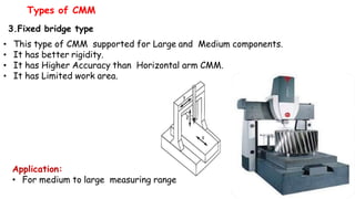
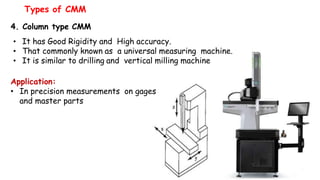
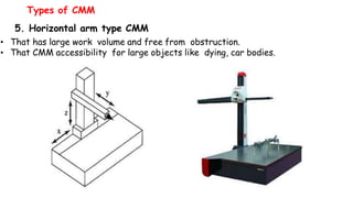
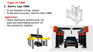
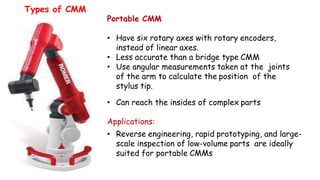
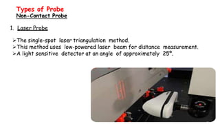
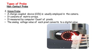
BAHIR DAR UNIVERSITY
BAHIR DAR INSTITUTE OF TECHNOLOGY (BiT)
FACULTY OF MECHANICAL AND INDUSTRIAL
ENGINEERING
Rapid Prototyping & Reverse Engineering
[MEng6123]
Reverse Engineering
Coordinate Measuring Machine (CMM)
Coordinate Measuring Machines (CMM)
• A Coordinate Measuring Machine (CMM)
is an electromechanical system designed
to perform coordinate metrology.
• CMM is a device for measuring the
physical geometrical characteristics of
an object.
Components of CMM
• Include three main components:
1.Main Structure
• which include three axes of motion
2.Probing system
3.Data collection and reduction system
• Application software
• Machine controller
• Desktop computer
Coordinate Measuring Machines (CMM)
CMM Features
Granite Table
• Structurally and thermally stable
material
• Low porosity
• Low moisture absorption
• Low coeff. of thermal expansion
• Superior strength
• Uniformity of texture
• Non-glaring surface
• Threaded table inserts
Coordinate Measuring Machines (CMM)
CMM Features
Air bearings
• Provided for ensuring friction free
travel to all axes
• Compressed air is forced through a
series of very small holes in a flat
bearing surface to provide a smooth
but controlled air cushion on which
the CMM can move in a frictionless
manner
Coordinate Measuring Machines (CMM)
CMM Applications
Metrology
• Linear Measurement
• Angular Measurement
• Geometrical Features
• Profile Checking
Stages of Inspection
• Receiving
• In-proses
• Final
Mode of Inspection Operation
• Manual
• Automated (DCC)
Purpose of Inspection
• First-piece approval
• Process Control
• Pre-assembly qualification of
parts
• Reverse Engineering
Location of Inspection
• Standard Room
• Machine Shop
• on Site
Coordinate Measuring Machines (CMM)
Types of CMM
• Cantilever Type
• Moving bridge type
• Fixed bridge type
• Column type
• Gantry type
• Horizontal arm type
• Portable type
1. Cantilever Type of CMM
Easy access to work and it has high desk volume.
It suitable for measuring the long and thin part.
Major disadvantage is bending caused by cantilever design
Types of CMM
Application:
• For checking sheet metal, cast iron and steel
parts in the automotive industry, aircraft
construction and shipbuilding.
2. Moving Bridge type
•Most widely used
•Disadvantage- with this design, the phenomenon of yawing
(sometimes called walking) can occur- affect the accuracy
•Advantage- reduce bending effect
Types of CMM
Application:
• For medium to large measuring range
3.Fixed bridge type
• This type of CMM supported for Large and Medium components.
• It has better rigidity.
• It has Higher Accuracy than Horizontal arm CMM.
• It has Limited work area.
Types of CMM
Application:
• For medium to large measuring range
4. Column type CMM
• It has Good Rigidity and High accuracy.
• That commonly known as a universal measuring machine.
• It is similar to drilling and vertical milling machine
Types of CMM
Application:
• In precision measurements on gages
and master parts
5. Horizontal arm type CMM
• That has large work volume and free from obstruction.
• That CMM accessibility for large objects like dying, car bodies.
Types of CMM
6. Gantry type CMM
• It can measure a large object.
• It has more accuracy than all other CMM.
Types of CMM
Application:
• Heavy machinery construction, car
body and mold making sectors of
the automotive industry
Portable CMM
• Have six rotary axes with rotary encoders,
instead of linear axes.
• Less accurate than a bridge type CMM
• Use angular measurements taken at the joints
of the arm to calculate the position of the
stylus tip.
• Can reach the insides of complex parts
Applications:
• Reverse engineering, rapid prototyping, and large-
scale inspection of low-volume parts are ideally
suited for portable CMMs
Types of CMM
Types of Probe
• Contact probe
• Hard probe
• Switching probes
• Measuring probes
• Non-contact probes
• Laser probe
• Vision probe
1. Hard Probe
 It has a variety of probe tip shape and size based on the application.
 Ball/Spherical shape probe used for establishing surface locations.
 Tapered or conical probe used for locating holes.
 Cylindrical probe used for checking slots and holes in sheet metal.
Types of Probe
Contact Probe
2. Switching Probes
• It is also called as Trigger type probe system.
• The “Buckling mechanism” is a three point bearing it
arranged at 120º around and circumference.
• Switching probe mostly used when an object has to be
measured very fast by a single point.
Types of Probe
Contact Probe
3. Measuring Probes
• It used for the large bridge type of CMM.
• It has also a “Buckling mechanism”
• It is a three dimensional probe.
• Stylus able to deflect in any direction
Types of Probe
Contact Probe
1. Laser Probe
The single-spot laser triangulation method.
This method uses low-powered laser beam for distance measurement.
A light sensitive detector at an angle of approximately 25º.
Types of Probe
Non-Contact Probe
2. Vision Probe
• A charge-coupled device (CCD) is usually employed in the camera.
• It consists of matrix arrays.
• It measured by computer ‘Count’ of pixels.
• The analog voltage value of each pixel converts to a digital value.
Types of Probe
Non-Contact Probe
CAUSES OF ERRORS IN CMM
• If the table and probes are in imperfect alignment;
• the probes may have a degree of run out and move up and down in the
Z-axis may occur perpendicularity errors.
• Therefore CMM should be calibrated with master plates before using
the machine.
• Dimensional errors of a CMM is influenced by;
• Straightness & perpendicularity of the guide ways.
• Scale division and adjustment.
• Probe length.
• Probe system calibration, repeatability, zero point setting and reversal error.
• Error due to digitization.
• Environment
• The length of the probe should be minimum to reduce deflection.
• The weight of the work piece may change the geometry of the guide
ways and therefore, the work piece must not exceed maximum
allowable weight.
• Variation in temperature of CMM, specimen and measuring lab influence
the uncertainly of measurements.
• Translation errors occur from error in the scale division and error in
straightness perpendicular to the corresponding axis direction.
• Perpendicularity error occurs if three axes are not orthogonal.
CAUSES OF ERRORS IN CMM

Lecture # 09 Coordinate Measuring Machine (CMM)

  • 1.
    BAHIR DAR UNIVERSITY BAHIRDAR INSTITUTE OF TECHNOLOGY (BiT) FACULTY OF MECHANICAL AND INDUSTRIAL ENGINEERING Rapid Prototyping & Reverse Engineering [MEng6123] Reverse Engineering Coordinate Measuring Machine (CMM)
  • 2.
    Coordinate Measuring Machines(CMM) • A Coordinate Measuring Machine (CMM) is an electromechanical system designed to perform coordinate metrology. • CMM is a device for measuring the physical geometrical characteristics of an object.
  • 3.
    Components of CMM •Include three main components: 1.Main Structure • which include three axes of motion 2.Probing system 3.Data collection and reduction system • Application software • Machine controller • Desktop computer Coordinate Measuring Machines (CMM)
  • 4.
    CMM Features Granite Table •Structurally and thermally stable material • Low porosity • Low moisture absorption • Low coeff. of thermal expansion • Superior strength • Uniformity of texture • Non-glaring surface • Threaded table inserts Coordinate Measuring Machines (CMM)
  • 5.
    CMM Features Air bearings •Provided for ensuring friction free travel to all axes • Compressed air is forced through a series of very small holes in a flat bearing surface to provide a smooth but controlled air cushion on which the CMM can move in a frictionless manner Coordinate Measuring Machines (CMM)
  • 6.
    CMM Applications Metrology • LinearMeasurement • Angular Measurement • Geometrical Features • Profile Checking Stages of Inspection • Receiving • In-proses • Final Mode of Inspection Operation • Manual • Automated (DCC) Purpose of Inspection • First-piece approval • Process Control • Pre-assembly qualification of parts • Reverse Engineering Location of Inspection • Standard Room • Machine Shop • on Site Coordinate Measuring Machines (CMM)
  • 7.
    Types of CMM •Cantilever Type • Moving bridge type • Fixed bridge type • Column type • Gantry type • Horizontal arm type • Portable type
  • 8.
    1. Cantilever Typeof CMM Easy access to work and it has high desk volume. It suitable for measuring the long and thin part. Major disadvantage is bending caused by cantilever design Types of CMM Application: • For checking sheet metal, cast iron and steel parts in the automotive industry, aircraft construction and shipbuilding.
  • 9.
    2. Moving Bridgetype •Most widely used •Disadvantage- with this design, the phenomenon of yawing (sometimes called walking) can occur- affect the accuracy •Advantage- reduce bending effect Types of CMM Application: • For medium to large measuring range
  • 10.
    3.Fixed bridge type •This type of CMM supported for Large and Medium components. • It has better rigidity. • It has Higher Accuracy than Horizontal arm CMM. • It has Limited work area. Types of CMM Application: • For medium to large measuring range
  • 11.
    4. Column typeCMM • It has Good Rigidity and High accuracy. • That commonly known as a universal measuring machine. • It is similar to drilling and vertical milling machine Types of CMM Application: • In precision measurements on gages and master parts
  • 12.
    5. Horizontal armtype CMM • That has large work volume and free from obstruction. • That CMM accessibility for large objects like dying, car bodies. Types of CMM
  • 13.
    6. Gantry typeCMM • It can measure a large object. • It has more accuracy than all other CMM. Types of CMM Application: • Heavy machinery construction, car body and mold making sectors of the automotive industry
  • 14.
    Portable CMM • Havesix rotary axes with rotary encoders, instead of linear axes. • Less accurate than a bridge type CMM • Use angular measurements taken at the joints of the arm to calculate the position of the stylus tip. • Can reach the insides of complex parts Applications: • Reverse engineering, rapid prototyping, and large- scale inspection of low-volume parts are ideally suited for portable CMMs Types of CMM
  • 15.
    Types of Probe •Contact probe • Hard probe • Switching probes • Measuring probes • Non-contact probes • Laser probe • Vision probe
  • 16.
    1. Hard Probe It has a variety of probe tip shape and size based on the application.  Ball/Spherical shape probe used for establishing surface locations.  Tapered or conical probe used for locating holes.  Cylindrical probe used for checking slots and holes in sheet metal. Types of Probe Contact Probe
  • 17.
    2. Switching Probes •It is also called as Trigger type probe system. • The “Buckling mechanism” is a three point bearing it arranged at 120º around and circumference. • Switching probe mostly used when an object has to be measured very fast by a single point. Types of Probe Contact Probe
  • 18.
    3. Measuring Probes •It used for the large bridge type of CMM. • It has also a “Buckling mechanism” • It is a three dimensional probe. • Stylus able to deflect in any direction Types of Probe Contact Probe
  • 19.
    1. Laser Probe Thesingle-spot laser triangulation method. This method uses low-powered laser beam for distance measurement. A light sensitive detector at an angle of approximately 25º. Types of Probe Non-Contact Probe
  • 20.
    2. Vision Probe •A charge-coupled device (CCD) is usually employed in the camera. • It consists of matrix arrays. • It measured by computer ‘Count’ of pixels. • The analog voltage value of each pixel converts to a digital value. Types of Probe Non-Contact Probe
  • 21.
    CAUSES OF ERRORSIN CMM • If the table and probes are in imperfect alignment; • the probes may have a degree of run out and move up and down in the Z-axis may occur perpendicularity errors. • Therefore CMM should be calibrated with master plates before using the machine. • Dimensional errors of a CMM is influenced by; • Straightness & perpendicularity of the guide ways. • Scale division and adjustment. • Probe length. • Probe system calibration, repeatability, zero point setting and reversal error. • Error due to digitization. • Environment
  • 22.
    • The lengthof the probe should be minimum to reduce deflection. • The weight of the work piece may change the geometry of the guide ways and therefore, the work piece must not exceed maximum allowable weight. • Variation in temperature of CMM, specimen and measuring lab influence the uncertainly of measurements. • Translation errors occur from error in the scale division and error in straightness perpendicular to the corresponding axis direction. • Perpendicularity error occurs if three axes are not orthogonal. CAUSES OF ERRORS IN CMM