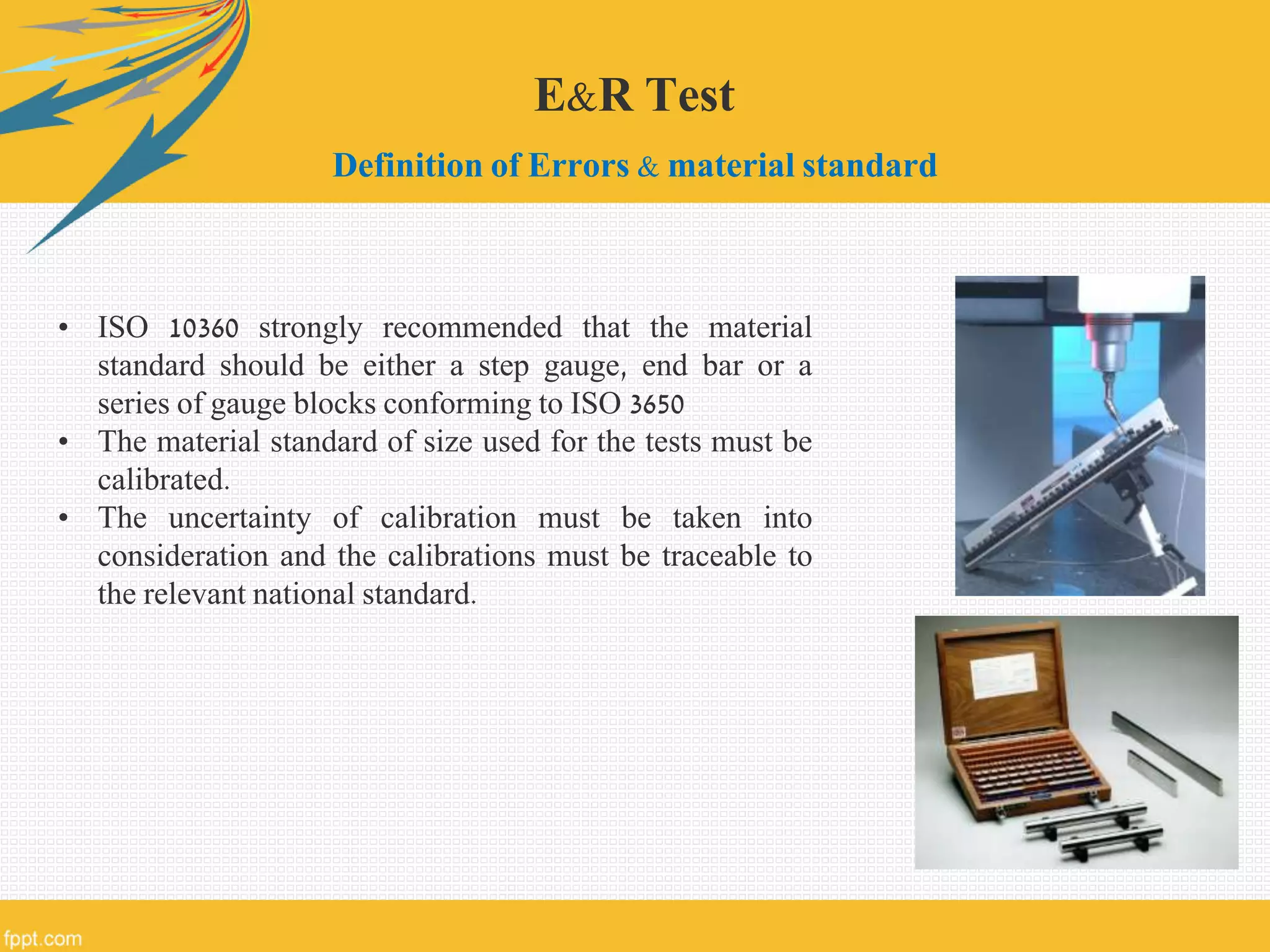
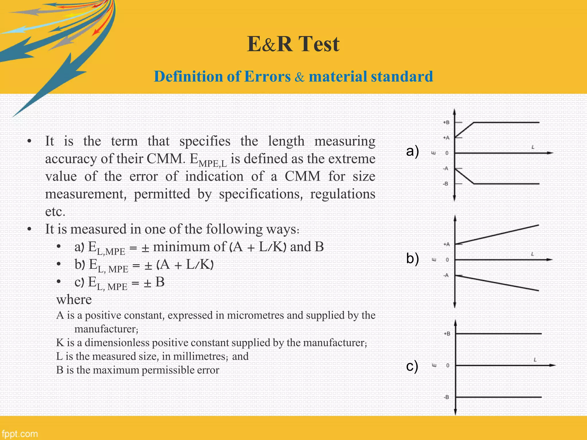
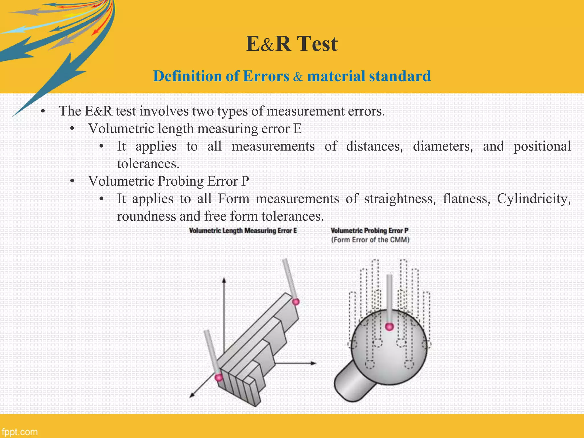
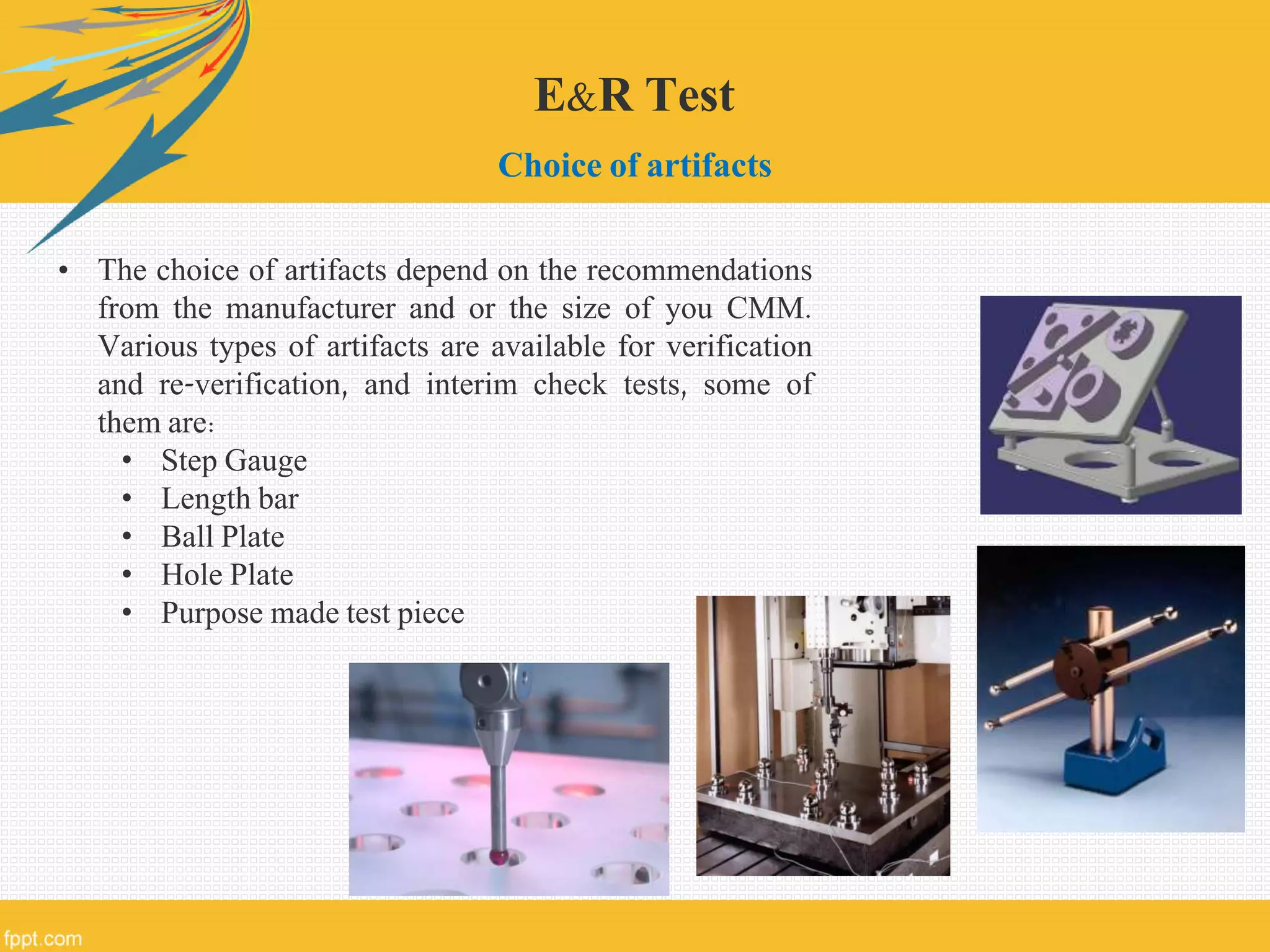
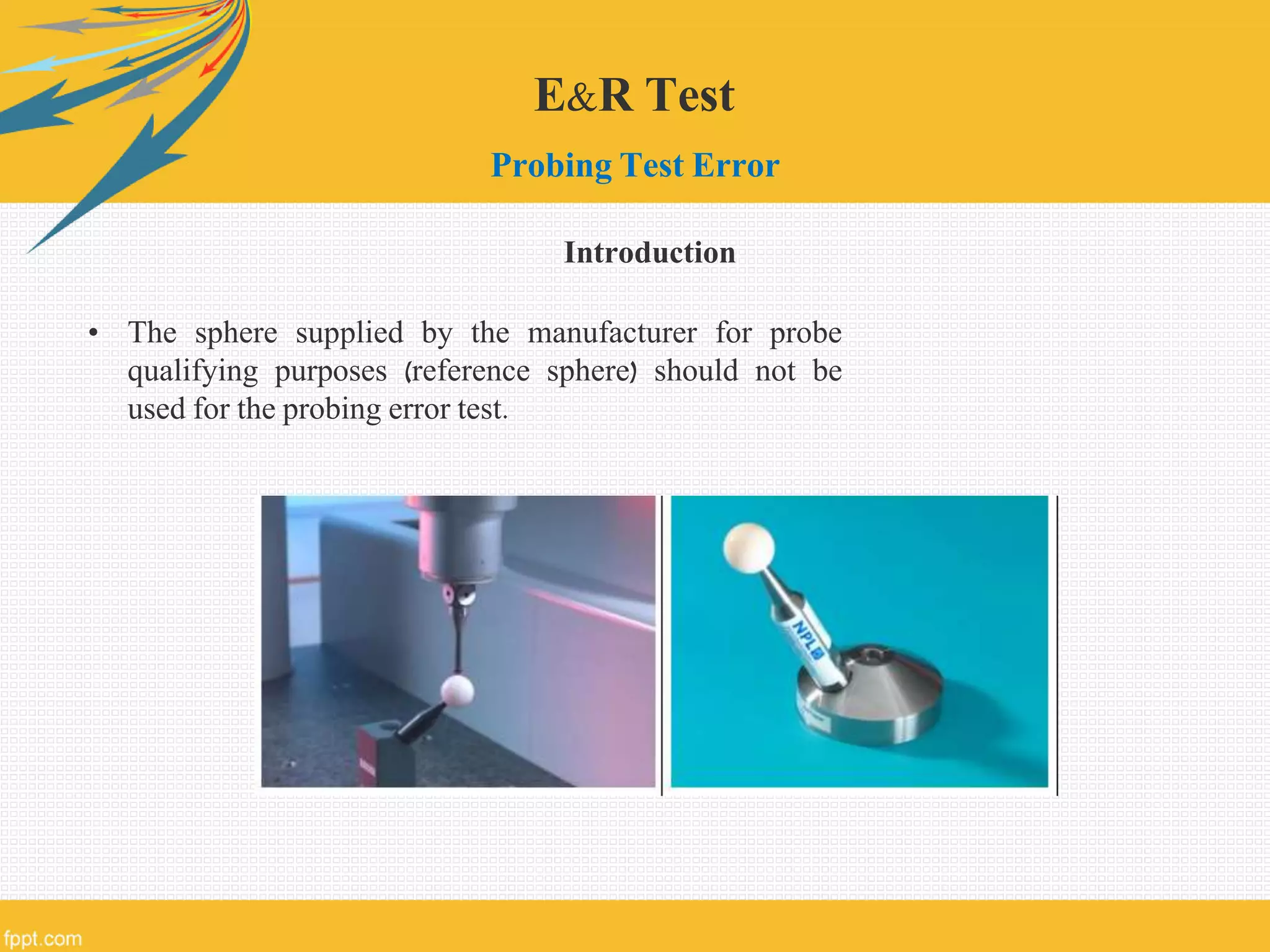
Downloaded 1,228 times
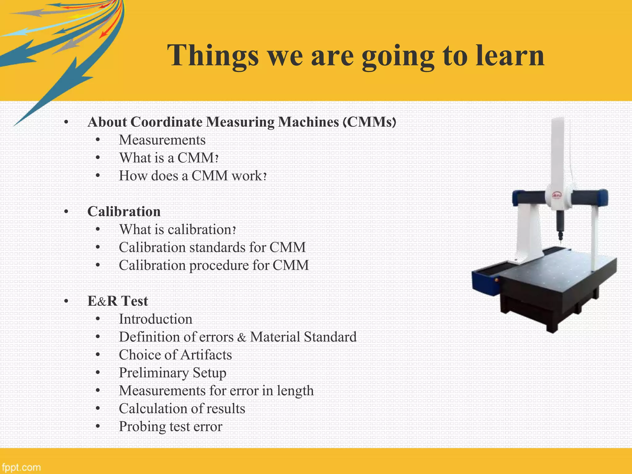
![About Coordinate Measuring Machines (CMM)
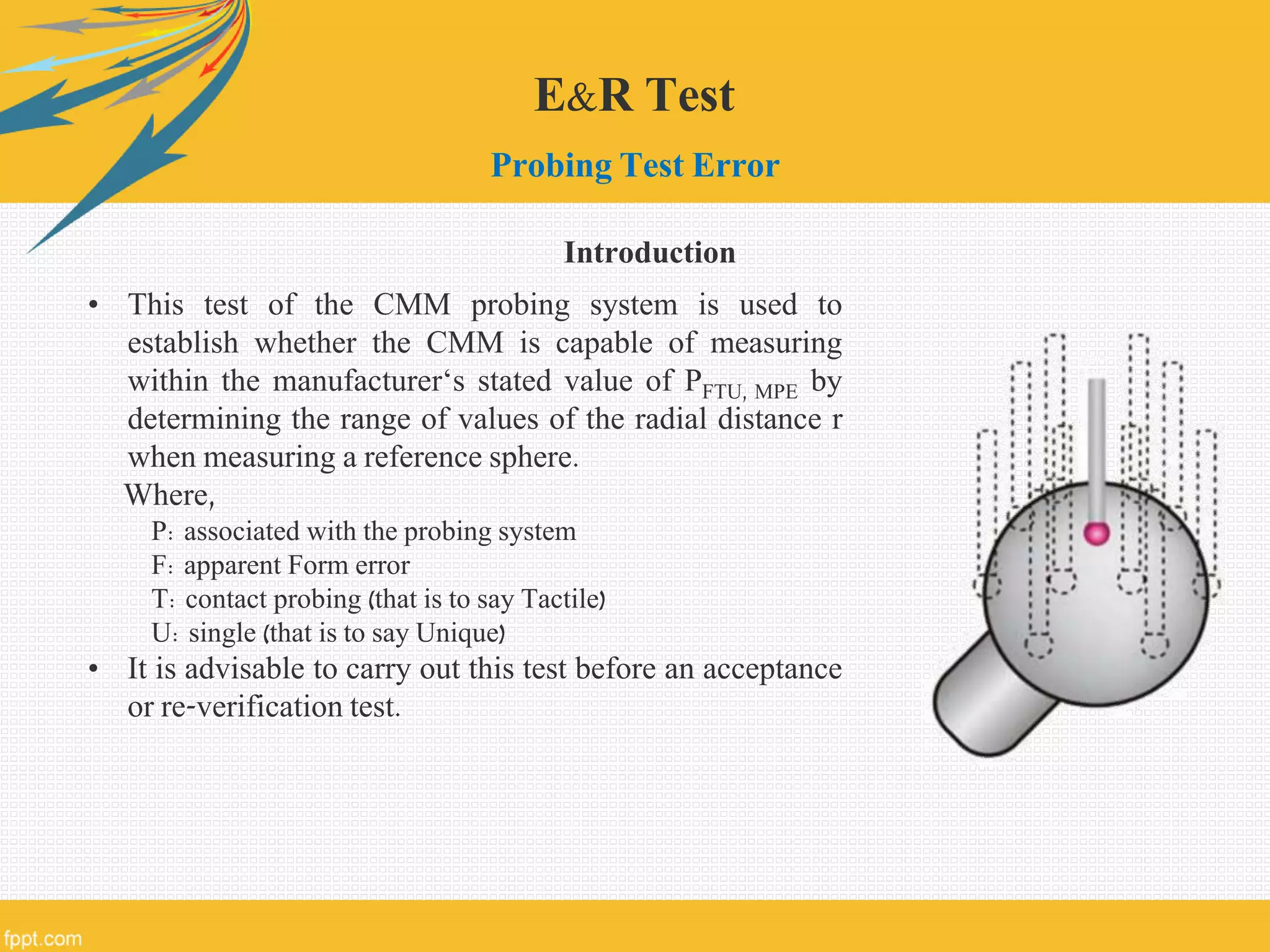
What is a CMM?
• Modern machines used for very accurate and precise
measurements
• CMM works on the principle of Coordinate Measuring i.e.
measurement based on collection of data points taken in a
Cartesian Coordinate System
• “The primary function of a CMM is to measure the actual
shape of a work piece, compare it against the desired
shape, and evaluate the metrological information such as
size, form, location, and orientation.” [Ref: Read ‘Notes’]](https://image.slidesharecdn.com/calibrationofcmm-150420092810-conversion-gate02/75/Calibration-of-Coordinate-Measuring-Machines-CMM-7-2048.jpg)


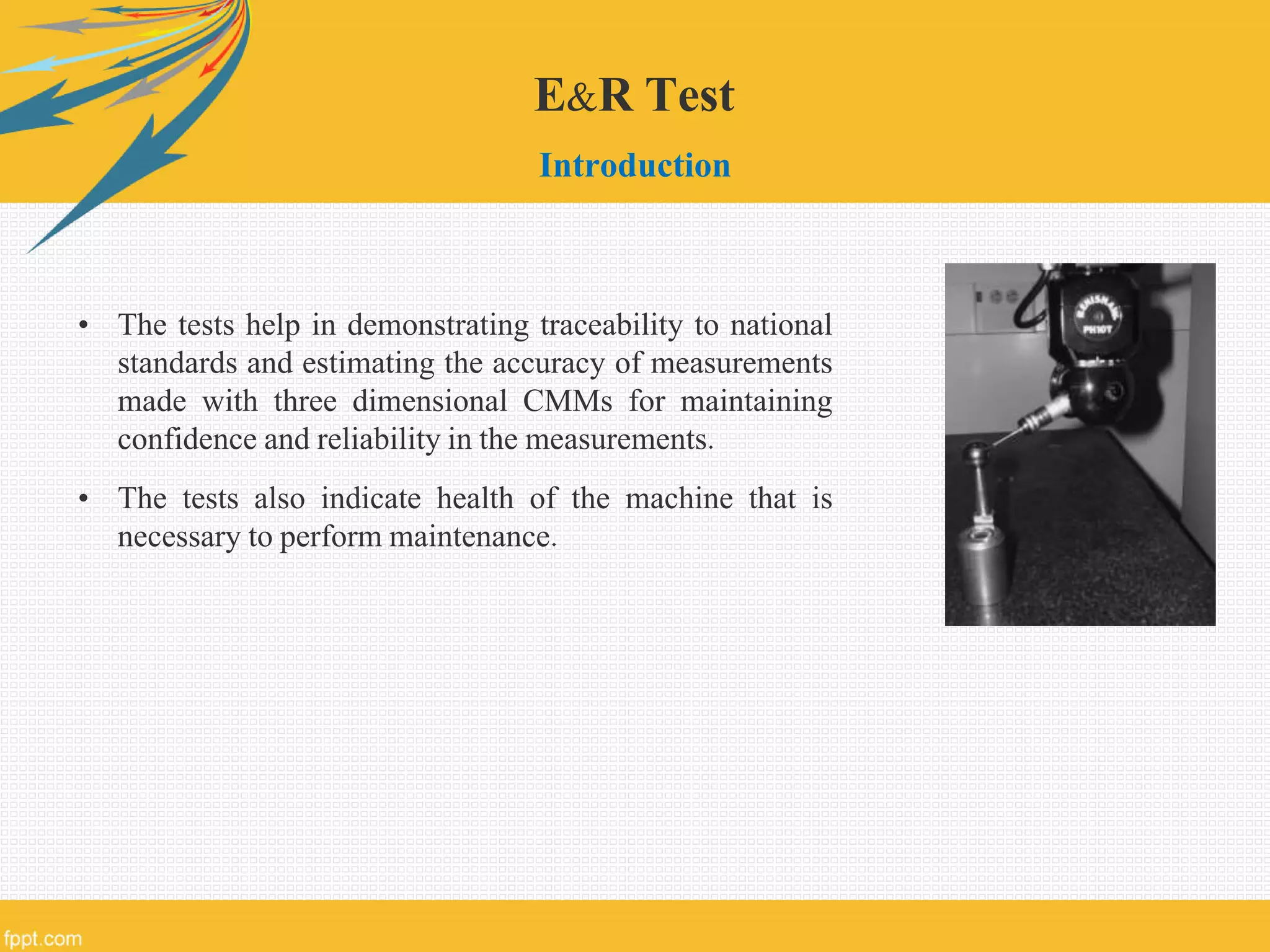
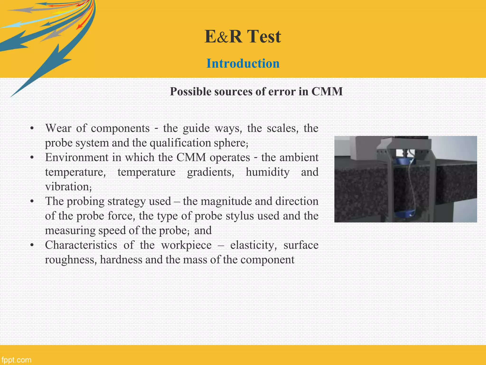
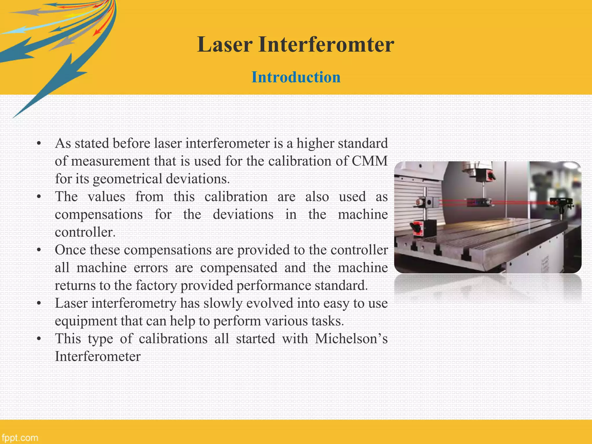
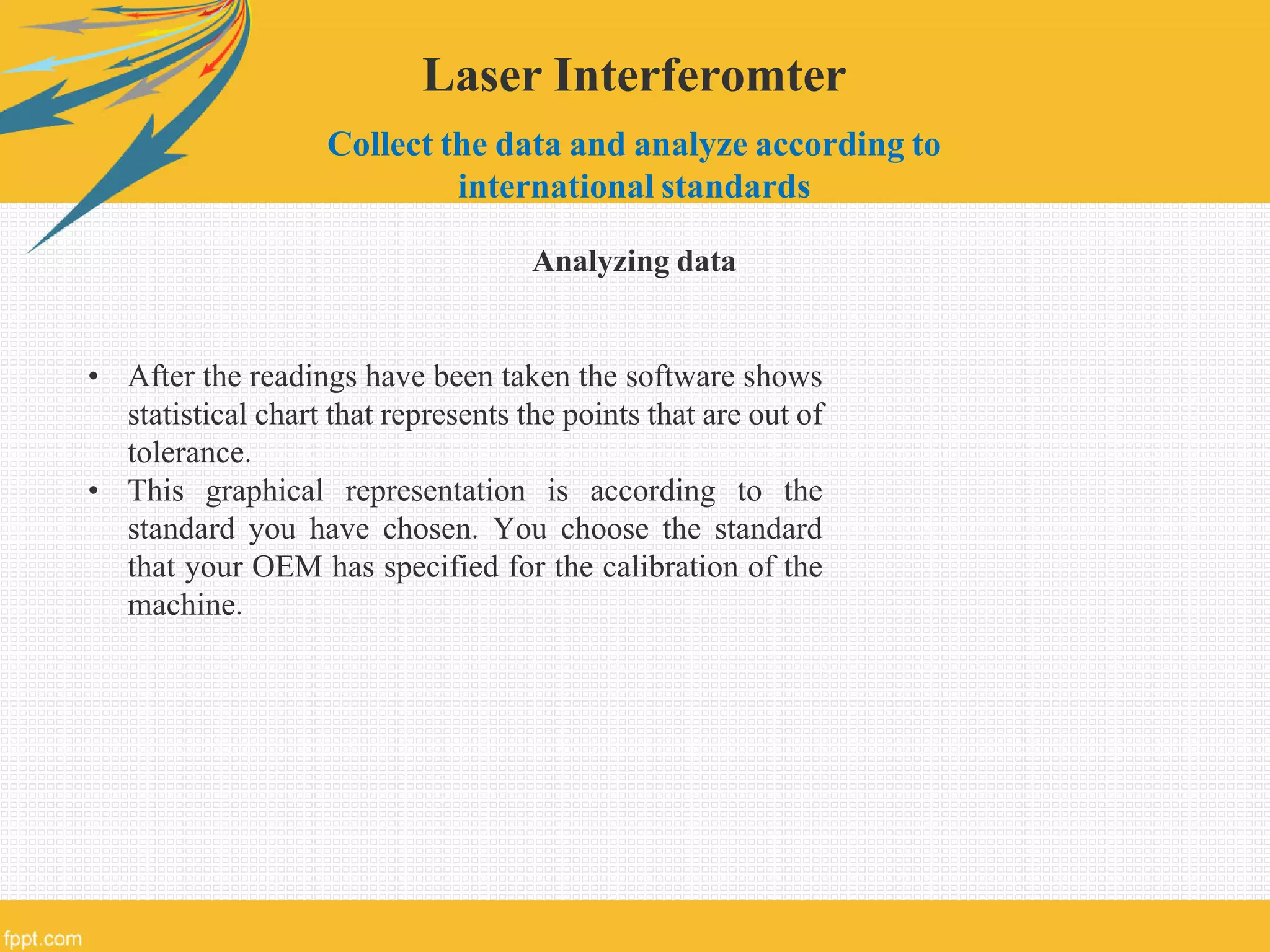
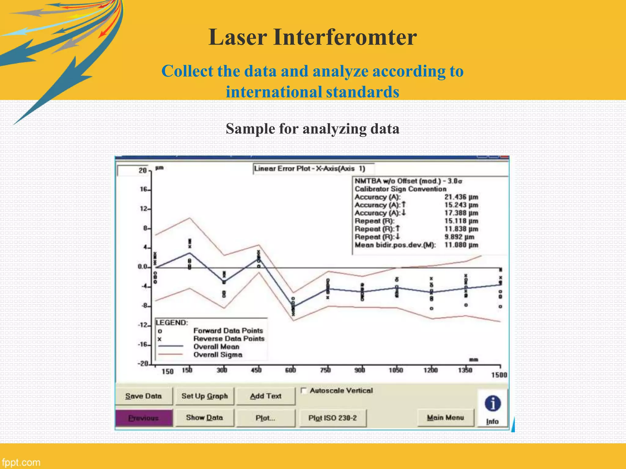

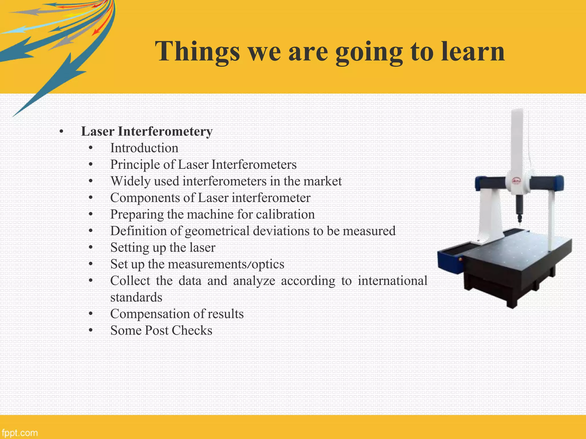
The document discusses the calibration of Coordinate Measuring Machines (CMMs) using the E&R test and laser interferometry, detailing the principles of CMM operation and the calibration standards involved. It outlines the calibration procedures, types of errors, and the significance of ensuring measurement accuracy through regular calibration according to established guidelines. Additionally, the document covers the setup and operation of laser interferometers for precise measurement and compensation of geometric deviations in CMMs.