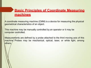
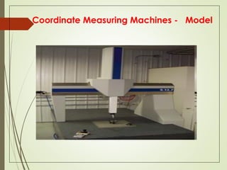
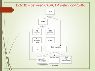
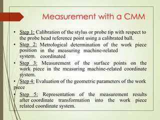
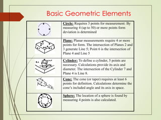
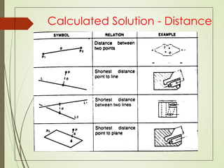
- A coordinate measuring machine (CMM) uses probes to inspect physical objects and measure their geometric features based on a coordinate system.
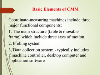
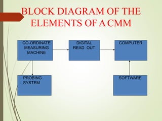
- CMMs can be manually operated or computer controlled, and use probes attached to movable axes to collect 3D coordinate data on measured points.
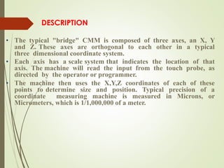
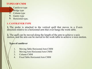
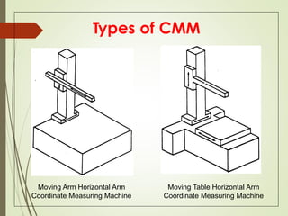
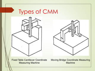
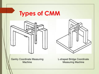
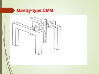
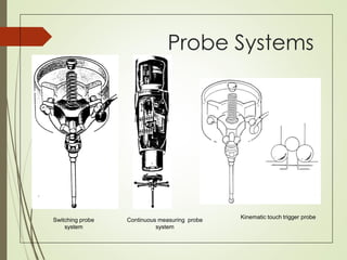
- Common CMM configurations include bridge, column, gantry, and horizontal arm styles, with probes that can be mechanical, optical, laser, or white light. CMMs provide highly accurate measurements in microns or micrometers.
Coordinate metrology is concerned with the measurement of the actual shape and dimensions of an object and comparing these with the desired shape and dimensions.
In this connection, coordinate metrology consists of the evaluation of the location, orientation, dimensions, and geometry of the part or object.
A Coordinate Measuring Machine (CMM) is an electromechanical system designed to perform coordinate metrology.
Calibration of Coordinate Measuring Machines (CMM)Hassan Habib
This presentation is made in an effort to impart information regarding the techniques used for the calibration of coordinate measuring machines. These versatile machines are today being used for the inspection of very precise and accurate mechanical components manufactured by keeping in view advanced geometrical dimensioning and tolerancing techniques.
This describes the mechanism of Computer Numerical Control along with its types, control system, motion system, Programming of CNC, G codes, Part programming, adaptive control machining etc.
A Coordinate measuring machine is an electromechanical system design to perform coordinate metrology.
CMMs are also considered as transducers that can convert physical measurements into electrical signals.
They are versatile in their capability to record measurement of complex profiles with high sensitivity (0.0025 mm) and speed.
The society of manufacturing engineers (SME) Defines CIM is integration of the total manufacturing enterprise through the use of integrated systems and data communications coupled with the new managerial philosophies that improve organizational and personal efficiency. CIM combines various technologies like computer-aided design (CAD) and computer-aided manufacturing (CAM) to provide an error-free manufacturing process that reduces manual labor and automates repetitive tasks.
THIS PPT CONTAIN VMC TRAINING AT GHANDHY COLLEGE SURAT. THIS INCLUDE ABOUT CNC MACHINE, AXIS IDENTIFICATIONS, PART PROGRAMMING, G CODES, M CODES,OPERATING OF VMC....SIMPLE DRAWING FOR VMC INCLUDING LINEAR N CIRCULAR INTERPOLATIONS
This material contains brief details about the CMM Probe, Types of probes, Parts of Probe, Multiple shapes of Stylus, Features of CMM probes, CMM Probes Specifications, Probe Calibration, Material specification of Probe, Standardization of Probe, Limitations of Probe.
I wish it would be helpful for your knowledge.
Surface finish measurement (mechanical measurement and metrology)Navroz Navodia
THIS ppt is good for understanding basics of surface measurement, it is good for undergraduate students persuing their bachlors in engineering,
the content of this ppt are as under
1) Basic terminology
2)techniques for surface finish measurement
3)comparison techniques like (visual scratch touch microscopic etc inspections)
4)direct instrument like (profilograph profilometer taylor hobson etc)
5)effect of surface finish on material strength
refer to this ppt for quick revision
good for gtu students specially
N3
APPLICATION OF MECHATRONICS IN COORDINATE MEASURING MACHINE.USE OF MULTI-SENSOR TECHNOLOGY.CMM IS USED TO MEASURE COORDINATE OF A WORKPIECE WITH THE HELP OF PROBE.CMM CAN BE CONTROLLED WITH THE HELP OF NUMERICAL CONTROL. INTRODUCTION TO 5 AXIS TECHNOLOGY.
ADVANTAGES OF CMM.TYPES OF CMM.
Applications Use of Coordinate Measuring Machine (CMM) for Measurement Produc...QUESTJOURNAL
Abstract: Coordinate Measuring Machine (measuring machine coordinates) is a measuring device multifunction high-speed (hight speed) the accuracy and efficiency in a high measurement, the working principle of Coordinate Measuring Machine CMM opposite of Computer Numerical Control CNC, the CNC machine coordinates that generating inserted chisel movement on the axes X, Y and Z on the workpiece, while the CMM contact between the probe with the workpiece to produce coordinates. In addition, if the CNC machines use ball bearings circulating (Circulated ball bearing) then the machine CMM using the annulment of air (air pad bearing) so movement is very smooth, to ensure the accuracy of construction CMM is made of rigid once One way to use a table grader made of granite as the reference plane. Cordinat Measuring Machine is measuring multi-function tools hight speed and accuracy and efficiency in Measuring result
CNC Programming for Begainer.
1.Easy Mehtod.
2.Complete Theoritical Knowledge.
3.Motion and coordinate system for NC machine.
4.Axes convention of VMC & HMC.
5.How to make Part Programming.
6.Coordinates System.
7.Programming Format.
8.List of G Codes And M Codes.
9.How to Use of Above Codes In Programme.
10.Reference Point and Return of Machine.
What is Coordinate Measuring Machine? CMM Types, Features, FunctionsVIEW
A Coordinate Measuring Machine (CMM) is a precision measuring metrology machine used in manufacturing and quality control processes to precisely measure the geometric characteristics of objects.
It operates on the principle of coordinate geometry, employing a probe to collect data points from the surface of an object to determine the dimensions, shapes, and positions of features, such as holes, slots, and surfaces.
CMMs are essential tools for ensuring that manufactured parts meet design specifications and quality standards.
COMPUTER AIDED QUALITY CONTROL AND HANDLING SYSTEMS.pptxDr.M BALA THEJA
COMPUTER AIDED QUALITY CONTROL AND HANDLING SYSTEMS
Inspection is normally used to examine whether a product conforms to the design standards specified for it. For a mechanical component, this would be probably concerned with the dimensions, surface texture and tolerances specified for the part. Non-conforming goods result in scrap, rework, and the loss of customer goodwill
Numerical Control (NC) machine tools – CNC types, constructional details, special features, machining centre, and part programming fundamentals CNC – manual part programming – micromachining – wafer machining
Search and Society: Reimagining Information Access for Radical FuturesBhaskar Mitra
The field of Information retrieval (IR) is currently undergoing a transformative shift, at least partly due to the emerging applications of generative AI to information access. In this talk, we will deliberate on the sociotechnical implications of generative AI for information access. We will argue that there is both a critical necessity and an exciting opportunity for the IR community to re-center our research agendas on societal needs while dismantling the artificial separation between the work on fairness, accountability, transparency, and ethics in IR and the rest of IR research. Instead of adopting a reactionary strategy of trying to mitigate potential social harms from emerging technologies, the community should aim to proactively set the research agenda for the kinds of systems we should build inspired by diverse explicitly stated sociotechnical imaginaries. The sociotechnical imaginaries that underpin the design and development of information access technologies needs to be explicitly articulated, and we need to develop theories of change in context of these diverse perspectives. Our guiding future imaginaries must be informed by other academic fields, such as democratic theory and critical theory, and should be co-developed with social science scholars, legal scholars, civil rights and social justice activists, and artists, among others.
DevOps and Testing slides at DASA ConnectKari Kakkonen
My and Rik Marselis slides at 30.5.2024 DASA Connect conference. We discuss about what is testing, then what is agile testing and finally what is Testing in DevOps. Finally we had lovely workshop with the participants trying to find out different ways to think about quality and testing in different parts of the DevOps infinity loop.
State of ICS and IoT Cyber Threat Landscape Report 2024 previewPrayukth K V
The IoT and OT threat landscape report has been prepared by the Threat Research Team at Sectrio using data from Sectrio, cyber threat intelligence farming facilities spread across over 85 cities around the world. In addition, Sectrio also runs AI-based advanced threat and payload engagement facilities that serve as sinks to attract and engage sophisticated threat actors, and newer malware including new variants and latent threats that are at an earlier stage of development.
The latest edition of the OT/ICS and IoT security Threat Landscape Report 2024 also covers:
State of global ICS asset and network exposure
Sectoral targets and attacks as well as the cost of ransom
Global APT activity, AI usage, actor and tactic profiles, and implications
Rise in volumes of AI-powered cyberattacks
Major cyber events in 2024
Malware and malicious payload trends
Cyberattack types and targets
Vulnerability exploit attempts on CVEs
Attacks on counties – USA
Expansion of bot farms – how, where, and why
In-depth analysis of the cyber threat landscape across North America, South America, Europe, APAC, and the Middle East
Why are attacks on smart factories rising?
Cyber risk predictions
Axis of attacks – Europe
Systemic attacks in the Middle East
Download the full report from here:
https://sectrio.com/resources/ot-threat-landscape-reports/sectrio-releases-ot-ics-and-iot-security-threat-landscape-report-2024/
Software Delivery At the Speed of AI: Inflectra Invests In AI-Powered QualityInflectra
In this insightful webinar, Inflectra explores how artificial intelligence (AI) is transforming software development and testing. Discover how AI-powered tools are revolutionizing every stage of the software development lifecycle (SDLC), from design and prototyping to testing, deployment, and monitoring.
Learn about:
• The Future of Testing: How AI is shifting testing towards verification, analysis, and higher-level skills, while reducing repetitive tasks.
• Test Automation: How AI-powered test case generation, optimization, and self-healing tests are making testing more efficient and effective.
• Visual Testing: Explore the emerging capabilities of AI in visual testing and how it's set to revolutionize UI verification.
• Inflectra's AI Solutions: See demonstrations of Inflectra's cutting-edge AI tools like the ChatGPT plugin and Azure Open AI platform, designed to streamline your testing process.
Whether you're a developer, tester, or QA professional, this webinar will give you valuable insights into how AI is shaping the future of software delivery.
JMeter webinar - integration with InfluxDB and GrafanaRTTS
Watch this recorded webinar about real-time monitoring of application performance. See how to integrate Apache JMeter, the open-source leader in performance testing, with InfluxDB, the open-source time-series database, and Grafana, the open-source analytics and visualization application.
In this webinar, we will review the benefits of leveraging InfluxDB and Grafana when executing load tests and demonstrate how these tools are used to visualize performance metrics.
Length: 30 minutes
Session Overview
-------------------------------------------
During this webinar, we will cover the following topics while demonstrating the integrations of JMeter, InfluxDB and Grafana:
- What out-of-the-box solutions are available for real-time monitoring JMeter tests?
- What are the benefits of integrating InfluxDB and Grafana into the load testing stack?
- Which features are provided by Grafana?
- Demonstration of InfluxDB and Grafana using a practice web application
To view the webinar recording, go to:
https://www.rttsweb.com/jmeter-integration-webinar
Accelerate your Kubernetes clusters with Varnish CachingThijs Feryn
A presentation about the usage and availability of Varnish on Kubernetes. This talk explores the capabilities of Varnish caching and shows how to use the Varnish Helm chart to deploy it to Kubernetes.
This presentation was delivered at K8SUG Singapore. See https://feryn.eu/presentations/accelerate-your-kubernetes-clusters-with-varnish-caching-k8sug-singapore-28-2024 for more details.
Connector Corner: Automate dynamic content and events by pushing a buttonDianaGray10
Here is something new! In our next Connector Corner webinar, we will demonstrate how you can use a single workflow to:
Create a campaign using Mailchimp with merge tags/fields
Send an interactive Slack channel message (using buttons)
Have the message received by managers and peers along with a test email for review
But there’s more:
In a second workflow supporting the same use case, you’ll see:
Your campaign sent to target colleagues for approval
If the “Approve” button is clicked, a Jira/Zendesk ticket is created for the marketing design team
But—if the “Reject” button is pushed, colleagues will be alerted via Slack message
Join us to learn more about this new, human-in-the-loop capability, brought to you by Integration Service connectors.
And...
Speakers:
Akshay Agnihotri, Product Manager
Charlie Greenberg, Host
Essentials of Automations: Optimizing FME Workflows with ParametersSafe Software
Are you looking to streamline your workflows and boost your projects’ efficiency? Do you find yourself searching for ways to add flexibility and control over your FME workflows? If so, you’re in the right place.
Join us for an insightful dive into the world of FME parameters, a critical element in optimizing workflow efficiency. This webinar marks the beginning of our three-part “Essentials of Automation” series. This first webinar is designed to equip you with the knowledge and skills to utilize parameters effectively: enhancing the flexibility, maintainability, and user control of your FME projects.
Here’s what you’ll gain:
- Essentials of FME Parameters: Understand the pivotal role of parameters, including Reader/Writer, Transformer, User, and FME Flow categories. Discover how they are the key to unlocking automation and optimization within your workflows.
- Practical Applications in FME Form: Delve into key user parameter types including choice, connections, and file URLs. Allow users to control how a workflow runs, making your workflows more reusable. Learn to import values and deliver the best user experience for your workflows while enhancing accuracy.
- Optimization Strategies in FME Flow: Explore the creation and strategic deployment of parameters in FME Flow, including the use of deployment and geometry parameters, to maximize workflow efficiency.
- Pro Tips for Success: Gain insights on parameterizing connections and leveraging new features like Conditional Visibility for clarity and simplicity.
We’ll wrap up with a glimpse into future webinars, followed by a Q&A session to address your specific questions surrounding this topic.
Don’t miss this opportunity to elevate your FME expertise and drive your projects to new heights of efficiency.
UiPath Test Automation using UiPath Test Suite series, part 4DianaGray10
Welcome to UiPath Test Automation using UiPath Test Suite series part 4. In this session, we will cover Test Manager overview along with SAP heatmap.
The UiPath Test Manager overview with SAP heatmap webinar offers a concise yet comprehensive exploration of the role of a Test Manager within SAP environments, coupled with the utilization of heatmaps for effective testing strategies.
Participants will gain insights into the responsibilities, challenges, and best practices associated with test management in SAP projects. Additionally, the webinar delves into the significance of heatmaps as a visual aid for identifying testing priorities, areas of risk, and resource allocation within SAP landscapes. Through this session, attendees can expect to enhance their understanding of test management principles while learning practical approaches to optimize testing processes in SAP environments using heatmap visualization techniques
What will you get from this session?
1. Insights into SAP testing best practices
2. Heatmap utilization for testing
3. Optimization of testing processes
4. Demo
Topics covered:
Execution from the test manager
Orchestrator execution result
Defect reporting
SAP heatmap example with demo
Speaker:
Deepak Rai, Automation Practice Lead, Boundaryless Group and UiPath MVP
Kubernetes & AI - Beauty and the Beast !?! @KCD Istanbul 2024Tobias Schneck
As AI technology is pushing into IT I was wondering myself, as an “infrastructure container kubernetes guy”, how get this fancy AI technology get managed from an infrastructure operational view? Is it possible to apply our lovely cloud native principals as well? What benefit’s both technologies could bring to each other?
Let me take this questions and provide you a short journey through existing deployment models and use cases for AI software. On practical examples, we discuss what cloud/on-premise strategy we may need for applying it to our own infrastructure to get it to work from an enterprise perspective. I want to give an overview about infrastructure requirements and technologies, what could be beneficial or limiting your AI use cases in an enterprise environment. An interactive Demo will give you some insides, what approaches I got already working for real.
Let's dive deeper into the world of ODC! Ricardo Alves (OutSystems) will join us to tell all about the new Data Fabric. After that, Sezen de Bruijn (OutSystems) will get into the details on how to best design a sturdy architecture within ODC.
"Impact of front-end architecture on development cost", Viktor TurskyiFwdays
I have heard many times that architecture is not important for the front-end. Also, many times I have seen how developers implement features on the front-end just following the standard rules for a framework and think that this is enough to successfully launch the project, and then the project fails. How to prevent this and what approach to choose? I have launched dozens of complex projects and during the talk we will analyze which approaches have worked for me and which have not.
2. A coordinate measuring machine (CMM) is a device for measuring the physical
geometrical characteristics of an object.
This machine may be manually controlled by an operator or it may be
computer controlled.
Measurements are defined by a probe attached to the third moving axis of this
machine. Probes may be mechanical, optical, laser, or white light, among
others.
Basic Principles of Coordinate Measuring
machines
3. DESCRIPTION
• The typical "bridge" CMM is composed of three axes, an X, Y
and Z. These axes are orthogonal to each other in a typical
three dimensional coordinate system.
• Each axis has a scale system that indicates the location of that
axis. The machine will read the input from the touch probe, as
directed by the operator or programmer.
• The machine then uses the X,Y,Z coordinates of each of these
points to determine size and position. Typical precision of a
coordinate measuring machine is measured in Microns, or
Micrometers, which is 1/1,000,000 of a meter.
4. •A coordinate measuring machine (CMM) is also a device
used in manufacturing and assembly processes to test a part or
assembly against the design intent. By precisely recording the X, Y,
and Z coordinates of the target, points are generated which can then
be analyzed via regression algorithms for the construction of features.
•These points are collected by using a probe that is positioned manually
by an operator or automatically via Direct Computer Control
(DCC). DCC CMMs can be programmed to repeatedly measure
identical parts, thus a CMM is a specialized form of industrial robot.
6. Basic Elements of CMM
Coordinate-measuring machines include three
major functional components:
1. The main structure (table & movable
frame) which include three axes of motion.
2. Probing system
3. Data collection system - typically includes
a machine controller, desktop computer and
application software
7. BLOCK DIAGRAM OF THE
ELEMENTS OFACMM
CO-ORDINATE
MEASURING
MACHINE
DIGITAL
READ OUT
COMPUTER
SOFTWAREPROBING
SYSTEM
8. Uses of CMM
They are often used for:
1. Dimensional measurement
2. Profile measurement
3. Angularity or orientation measurement
4. Depth mapping
5. Digitizing or imaging
6. Shaft measurement
10. ADVANTAGES OF USING CMM
FLEXIBILITY:
Co-ordinate measuring machines are essentially universal measuring machines and
do not need to be dedicated to any single or particular measuring task.
They can measure practically any dimensional characteristic of virtually any
part configuration, including cams, gears, and contoured surfaces.
No special fixtures or gages are required; because electronic probe contact is light,
most parts can be inspected without being clamped to a surface plate.
REDUCED SETUP TIME:
Establishing part alignment and appropriate reference points are very time
consuming with conventional surface-plate inspection techniques.
These procedures are greatly simplified or virtually eliminated through
software available on computer-assisted or computer-controlled CMMs.
11. IMPROVEDACCURACY
All measurements on a CMM are taken from a common geometrically fixed
measuring system, eliminating the introduction and accumulation of errors that
can result with hard gage inspection methods and transfer techniques.
Moreover, measuring all significant features of a part in one setup prevents
the introduction of errors due to setup changes.
In the part-program-assisted mode, the operator positions the machine; once the
initial position has been set, the machine is under the control of a program that
eliminates operator choice.
In the Computer Numerically Controlled (CNC) mode, motor-driven machines
run totally unattended by operators.
Also, automatic data recording, available on most machines, prevents errors in
transcribing readings to the inspection report.
This all adds up to the fact that less skilled operators can be readily instructed to
perform relatively complex inspection procedures.
12. IMPROVED PRODUCTIVITY
All the factors previously mentioned help to make CMMs more productive
than
conventional inspection techniques.
Further dramatic productivity improvements are realized through the computational
and analytical capabilities of associated data handling systems, including
calculators and all levels of computers.
13.
14. • All CMMs will have three moving elements of which one is capable of moving in x-
axis, another in y-axis and another in z-axis with respect to each other.
• Each moving element is also fitted with a linear measurement transducer for positional
feedback, with the help of which we can have the co-ordinate of a particular position
with respect to a reference.
• The moving elements can be moved by means of frictionless air bearings or mechanical
bearings.
• The Job to be measured will be mounted over a table made of granite because of
its stability in various temperatures.
• The work table of the machine generally consists of tapped holes to facilitate clamping
and locating of parts.
• A total of 11 different machine configurations exist; however, some
configurations are modifications of one of the five primary configurations:
of these
15. MACHINE CONFIGURATIONS
A v ariety of machine configurations is available from
the manufacturers of CMMs.
Each configuration has advantages that make it suitable
for particular applications.
A total of 11 different machine configurations exist;
however, some of these configurations are modifications of
one of the four primary configurations: bridge,
column, gantry, and horizontal arm.
16. TYPES OF CMM
1.
2.
3.
4.
5.
Cantilever type
Bridge type
Column type
Gantry type
Horizontal type.
1. CANTILEVER TYPE
1. The probe is attached to the vertical quill that moves in a Z-axis
direction relative to a horizontal arm that over hangs the work table.
2. The quill can be moved along the length of the arm to achieve y-axis
motion, and the arm can be moved to the work table to achieve x-axis motion.
Types of cantilever
1. Moving Table Horizontal Arm CMM
2. MovingArm HorizontalArm CMM
3. Column CMM
4. Fixed Table HorizontalArm CMM
17. Types of CMM
Moving Arm Horizontal Arm
Coordinate Measuring Machine
Moving Table Horizontal Arm
Coordinate Measuring Machine
22. COLUMN:
Column-type CMMs are similar in construction to
accurate jig boring machines.
The column moves in a vertical (Z) direction only, and
a two-axis saddle permits movement in the horizontal
(X and Y) direction.
Column-type CMMs are often referred to as
universal measuring machines rather than
CMMs by manufacturers and are considered gage-
room instruments rather than production-floor m/c.
38. Data flow between CAD/CAM system and CMM
CAD
CAM
NC
processor
CMM
processor
CMM
NC
machine
center
Part
CMM Inspection
Update NC
part program
Flag tool room Tool
management
and planning
Theoritical part
Part Program
for minor tooling wear
and machine
adjustment
for major flaws
39. Measurement with a CMM
• Step 1: Calibration of the stylus or probe tip with respect to
the probe head reference point using a calibrated ball.
• Step 2:
position
system.
Metrological determination of the work piece
in the measuring machine-related
coordinated
• Step 3: Measurement of the surface points on the
work piece in the measuring machine-related coordinate
system.
• Step 4: Evaluation of the geometric parameters of the work
piece
• Step 5: Representation of the measurement results
after coordinate transformation into the work piece
related coordinate system.
40. Basic Geometric Elements
Circle: Requires 3 points for measurement: By
measuring 4 (up to 50) or more points form
deviation is determined
Plane: Planar measurements require 4 or more
points for form. The intersection of Planes 2 and
3 generate Line 5; Point 6 is the intersection of
Plane 4 and Line 5
Cylinder: To define a cylinder, 5 points are
necessary. Calculations provide its axis and
diameter. The intersection of the Cylinder 7 and
Plane 4 is Line 8.
Cone: The cone (or taper) requires at least 6
points for definition. Calculations determine the
cone’s included angle and its axis in space.
Sphere: The location of a sphere is found by
measuring 4 points is also calculated.