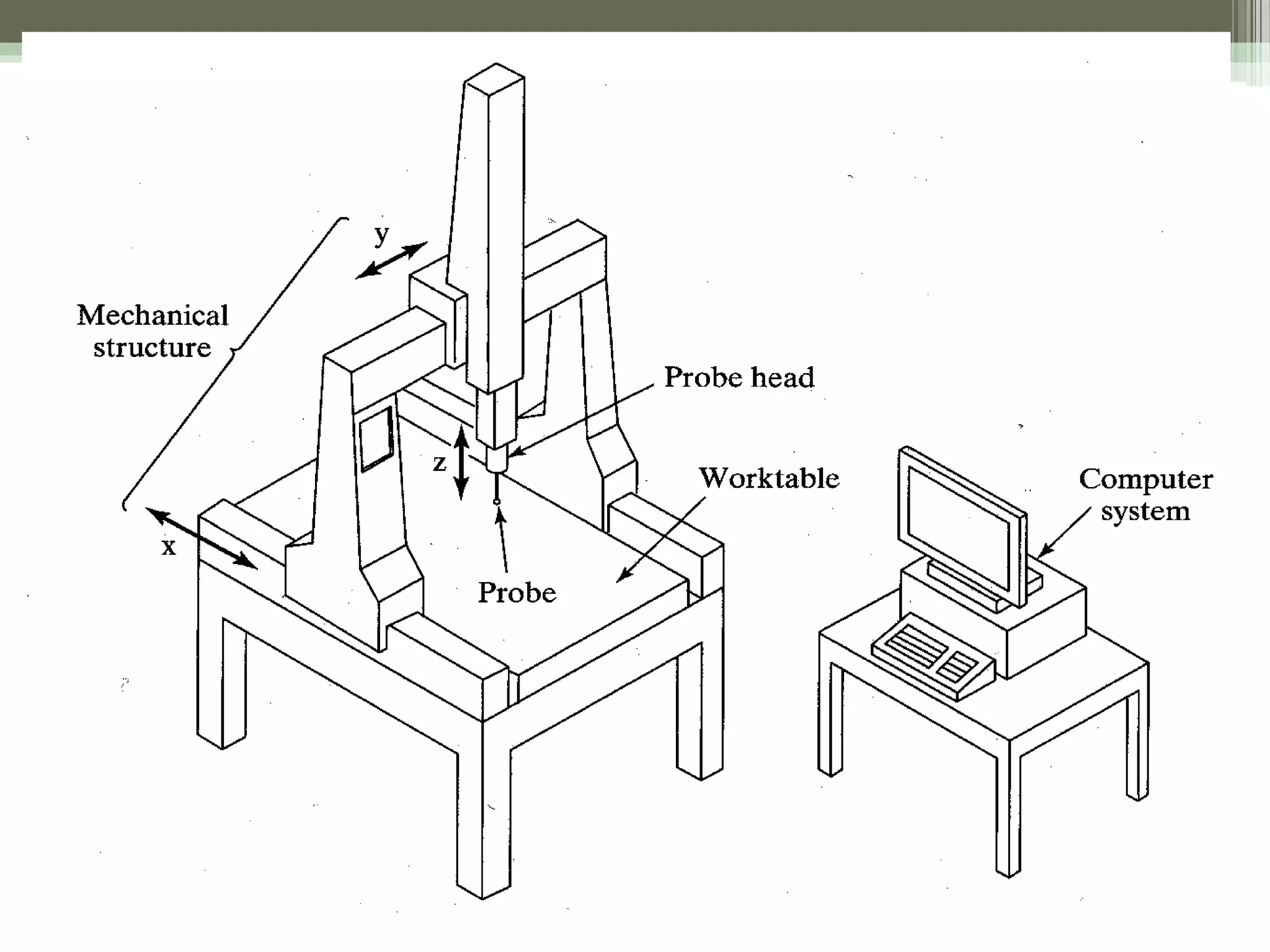
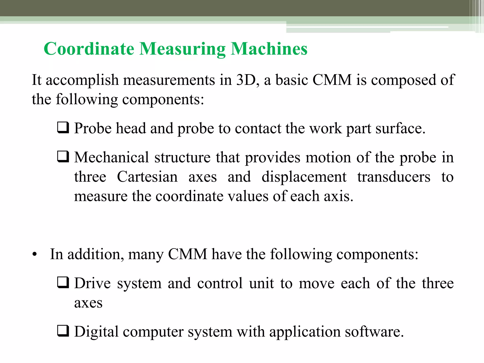
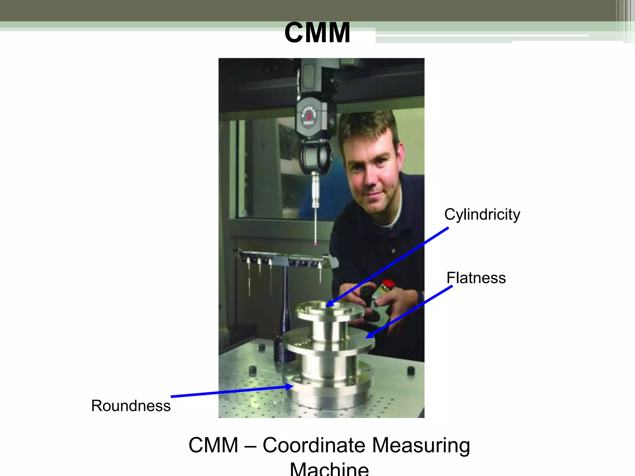
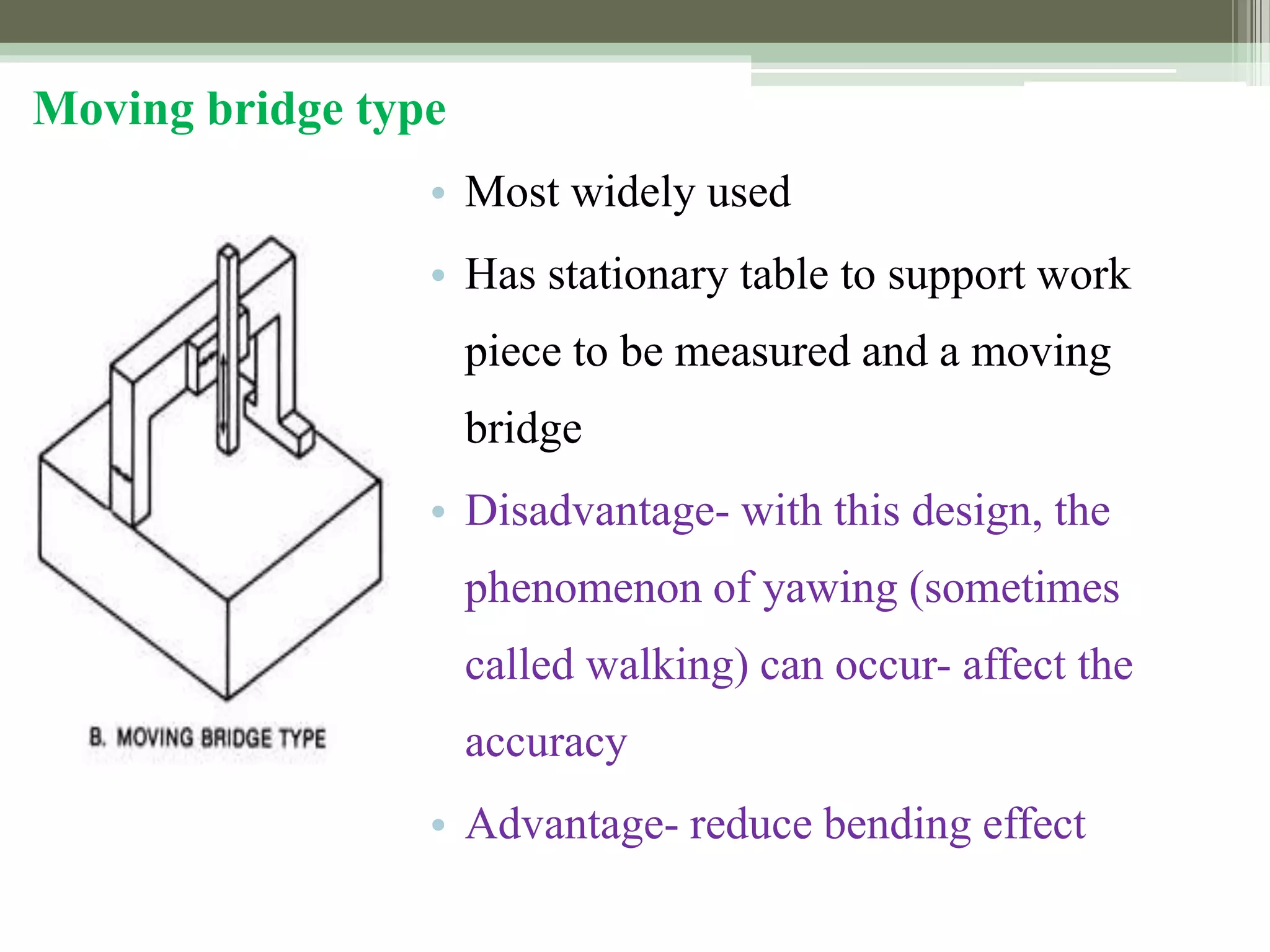
Advances in Metrology
RV
Introduction
1. Length bar measuring machine.
2. Universal measuring machine.
3. Co-ordinate measuring machine.
4. Computer controlled co-ordinate measuring
Co-ordinate measuring machine.
• It is concerned with the measurement of the actual
shape and dimensions of an object and comparing
these with the desired shape and dimensions.
• In this connection, coordinate metrology consists of
the evaluation of the location, orientation,
dimensions, and geometry of the part or object.
• A Coordinate Measuring Machine (CMM) is an
electromechanical system designed to perform
coordinate metrology.
Features of CMM Software
• Measurement of diameter, center distance, length.
• Measurement of plane and spatial carvers.
• Minimum CNC programmed.
• Data communications.
• Digital input and output command.
• Program me for the measurement of spur, helical,
bevel and hypoid gears.
• Interface to CAD software
Development of CMM
• First appeared in 1960 3D device with DRO
display introduced by DEA, Italy.
• Ferranti metrology Cantilever CMM, Scotland
• First bridge CMM, LK Tool, UK
Coordinate Measuring Machine (CMM)
Measuring machine consisting of a contact probe and a
mechanism to position the probe in three-dimensions
relative to surfaces and features of a work part
The probe is fastened to a structure that allows
movement relative to the part
Part is fixture on worktable connected to structure
The location coordinates of the probe can be accurately
recorded as it contacts the part surface to obtain part
geometry data
Coordinate Measuring Machines
• A CMM consists of a constant probe that can be
positioned in 3D space relative to the surface of a
work part, and the x, y, and z coordinates of the probe
can be accurately and precisely recorded to obtain
dimensional data concerning the part geometry
It accomplish measurements in 3D, a basic CMM is composed of
the following components:
 Probe head and probe to contact the work part surface.
 Mechanical structure that provides motion of the probe in
three Cartesian axes and displacement transducers to
measure the coordinate values of each axis.
• In addition, many CMM have the following components:
 Drive system and control unit to move each of the three
axes
 Digital computer system with application software.
Coordinate Measuring Machines
CMM
CMM – Coordinate Measuring
Flatness
Roundness
Cylindricity
CMM Mechanical Structure
(a) Cantilever (b) Moving bridge (c) Fixed bridge
CMM Mechanical Structure
(d) Horizontal Arm (e) Gantry (f) Column
Cantilever type
• A vertical probe moves in the z-axis
• Carried by a cantilevered arm that moves in the y-
axis
• This arm also moves laterally through the x-axis
• Advantage- a fixed table allows good accessibility
to the work piece
• Disadvantage- the bending caused by the cantilever
design
• The cantilever design offers a long table with
relatively small measuring ranges in the other two
axis.
• Suitable for measuring long, thin part
Moving bridge type
• Most widely used
• Has stationary table to support work
piece to be measured and a moving
bridge
• Disadvantage- with this design, the
phenomenon of yawing (sometimes
called walking) can occur- affect the
accuracy
• Advantage- reduce bending effect
Fixed bridge type
• In the fixed bridge configuration,
the bridge is rigidly attached to the
machine bed
• This design eliminates the
phenomenon of walking and
provides high rigidity
Column type
• Often referred to as universal
measuring machine instead of CMM
• The column type CMM construction
provides exceptional rigidity and
accuracy
• These machines are usually reserved
for gauge rooms rather than
inspection
Horizontal arm type
• Unlike the previous machines, the
basic horizontal arm-type CMM
• Also referred to as layout machine
• Has a moving arm, and the probe is
carried along the y-axis
• Advantage- provides a large area,
unobstructed work area
• Ideal configuration for measurement
of automobile parts
Gantry type
• The support of work piece is independent of the
x and y axes, both are overhead, supported by
four vertical columns rising from the floor
• This setup allows you to walk along the work
piece with the probe, which is helpful for
extremely large pieces
ADVANTAGES
• The inspection rate is increased.
• Accuracy is more.
• Operators error can be minimized.
• Skill requirements of the operator is reduced.
• Reduced inspection fix Turing and maintenance cost.
• Reduction in calculating and recording time.
• Reduction in set up time.
• No need of separate go / no go gauges for each feature.
• Reduction of scrap and good part rejection.
• Reduction in off line analysis time.
DISADVANTAGES
• The table and probe may not be in perfect alignment.
• The probe may have run out.
• The probe moving in Z-axis may have some
perpendicular errors.
• Probe while moving in X and Y direction may not be
square to each other.
• There may be errors in digital system.
APPLICATIONS
1) Co-ordinate measuring machines find applications in
automobile, machine tool, electronics, space and many other
large companies.
2) These machines are best suited for the test and inspection of
test equipment, gauges and tools.
3) For aircraft and space vehicles, hundred percent inspections is
carried out by using CMM.
4) CMM can be used for determining dimensional accuracy of
the components.
5) These are ideal for determination of shape and position,
maximum metal condition,linkage of results etc. which cannot do
in conventional machines.
6) CMM can also be used for sorting tasks to achieve optimum
pairing of components within tolerance limits.
7) CMMs are also best for ensuring economic viability of NC
machines by reducing their downtime for inspection results. They
also help in reducing cost, rework cost at the appropriate time
with a suitable CMM.

Advances in metrology i

  • 1.
  • 2.
    Introduction 1. Length barmeasuring machine. 2. Universal measuring machine. 3. Co-ordinate measuring machine. 4. Computer controlled co-ordinate measuring
  • 3.
    Co-ordinate measuring machine. •It is concerned with the measurement of the actual shape and dimensions of an object and comparing these with the desired shape and dimensions. • In this connection, coordinate metrology consists of the evaluation of the location, orientation, dimensions, and geometry of the part or object. • A Coordinate Measuring Machine (CMM) is an electromechanical system designed to perform coordinate metrology.
  • 4.
    Features of CMMSoftware • Measurement of diameter, center distance, length. • Measurement of plane and spatial carvers. • Minimum CNC programmed. • Data communications. • Digital input and output command. • Program me for the measurement of spur, helical, bevel and hypoid gears. • Interface to CAD software
  • 5.
    Development of CMM •First appeared in 1960 3D device with DRO display introduced by DEA, Italy. • Ferranti metrology Cantilever CMM, Scotland • First bridge CMM, LK Tool, UK
  • 6.
    Coordinate Measuring Machine(CMM) Measuring machine consisting of a contact probe and a mechanism to position the probe in three-dimensions relative to surfaces and features of a work part The probe is fastened to a structure that allows movement relative to the part Part is fixture on worktable connected to structure The location coordinates of the probe can be accurately recorded as it contacts the part surface to obtain part geometry data
  • 7.
    Coordinate Measuring Machines •A CMM consists of a constant probe that can be positioned in 3D space relative to the surface of a work part, and the x, y, and z coordinates of the probe can be accurately and precisely recorded to obtain dimensional data concerning the part geometry
  • 9.
    It accomplish measurementsin 3D, a basic CMM is composed of the following components:  Probe head and probe to contact the work part surface.  Mechanical structure that provides motion of the probe in three Cartesian axes and displacement transducers to measure the coordinate values of each axis. • In addition, many CMM have the following components:  Drive system and control unit to move each of the three axes  Digital computer system with application software. Coordinate Measuring Machines
  • 10.
    CMM CMM – CoordinateMeasuring Flatness Roundness Cylindricity
  • 11.
    CMM Mechanical Structure (a)Cantilever (b) Moving bridge (c) Fixed bridge
  • 12.
    CMM Mechanical Structure (d)Horizontal Arm (e) Gantry (f) Column
  • 13.
    Cantilever type • Avertical probe moves in the z-axis • Carried by a cantilevered arm that moves in the y- axis • This arm also moves laterally through the x-axis • Advantage- a fixed table allows good accessibility to the work piece • Disadvantage- the bending caused by the cantilever design • The cantilever design offers a long table with relatively small measuring ranges in the other two axis. • Suitable for measuring long, thin part
  • 14.
    Moving bridge type •Most widely used • Has stationary table to support work piece to be measured and a moving bridge • Disadvantage- with this design, the phenomenon of yawing (sometimes called walking) can occur- affect the accuracy • Advantage- reduce bending effect
  • 15.
    Fixed bridge type •In the fixed bridge configuration, the bridge is rigidly attached to the machine bed • This design eliminates the phenomenon of walking and provides high rigidity
  • 16.
    Column type • Oftenreferred to as universal measuring machine instead of CMM • The column type CMM construction provides exceptional rigidity and accuracy • These machines are usually reserved for gauge rooms rather than inspection
  • 17.
    Horizontal arm type •Unlike the previous machines, the basic horizontal arm-type CMM • Also referred to as layout machine • Has a moving arm, and the probe is carried along the y-axis • Advantage- provides a large area, unobstructed work area • Ideal configuration for measurement of automobile parts
  • 18.
    Gantry type • Thesupport of work piece is independent of the x and y axes, both are overhead, supported by four vertical columns rising from the floor • This setup allows you to walk along the work piece with the probe, which is helpful for extremely large pieces
  • 20.
    ADVANTAGES • The inspectionrate is increased. • Accuracy is more. • Operators error can be minimized. • Skill requirements of the operator is reduced. • Reduced inspection fix Turing and maintenance cost. • Reduction in calculating and recording time. • Reduction in set up time. • No need of separate go / no go gauges for each feature. • Reduction of scrap and good part rejection. • Reduction in off line analysis time.
  • 21.
    DISADVANTAGES • The tableand probe may not be in perfect alignment. • The probe may have run out. • The probe moving in Z-axis may have some perpendicular errors. • Probe while moving in X and Y direction may not be square to each other. • There may be errors in digital system.
  • 22.
    APPLICATIONS 1) Co-ordinate measuringmachines find applications in automobile, machine tool, electronics, space and many other large companies. 2) These machines are best suited for the test and inspection of test equipment, gauges and tools. 3) For aircraft and space vehicles, hundred percent inspections is carried out by using CMM. 4) CMM can be used for determining dimensional accuracy of the components. 5) These are ideal for determination of shape and position, maximum metal condition,linkage of results etc. which cannot do in conventional machines.
  • 23.
    6) CMM canalso be used for sorting tasks to achieve optimum pairing of components within tolerance limits. 7) CMMs are also best for ensuring economic viability of NC machines by reducing their downtime for inspection results. They also help in reducing cost, rework cost at the appropriate time with a suitable CMM.