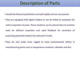
COORDINATE MEASURING MACHINE
Coordinate-measuring machine
A coordinate measuring machine is a device for measuring the
physical geometrical characteristics of an object. This machine
may be manually controlled by an operator or it may be
computer controlled. Measurements are defined by a probe
attached to the third moving axis of this machine. Probes may
be mechanical, optical, laser, or white light, amongst others. A
machine which takes readings in six degrees of freedom and
displays these readings in mathematical form is known as a
CMM.
Technical facts
• Coordinate-measuring machines include three main components.
• The main structure which include three axes of motion.
• Probing system.
• Data collection and reduction system - typically includes a machine
controller, desktop computer and application software.
Working principle of CMM
A coordinate measuring machine is also a device
used in manufacturing and assembly processes to test a part
or assembly against the design intent. By precisely recording
the X, Y, and Z coordinates of the target, points are generated
which can then be analyzed via regression algorithms for the
construction of features. These points are collected by using
a probe that is positioned manually by an operator or
automatically via Direct Computer Control .
Main parts of CMM
•Air Bearing
•Scales and Encoders
•Probing system
•Servo motors
•Control system
•Joystick
•Software(Tangram)
Advantages of CMM
• Flexibility
• Reduced Setup Time
• Single Setup
• Accuracy
• Reduced Operator Influence
• Improved Productivity
Configuration of CMM
• Model: - Spectra 5.6.4. CNC
• Scale Regulation = 0.5 μm
• Machine accuracy = (± 2.5 + L/250) μm; (L: Standard length in mm)
• Angular accuracy = 1” (One second)
• Granite flatness = 2 micron per meter square
• Granite grade = zero grade
• Probing system = MS2DI
• M/c version = CNC version
• M/c working volume = X = 500 mm; Y = 600 mm; Z = 400 mm
• Controller name = Renishaw UCC (Universal CMM Controller) lite-2 (U.K.)
• Coordinate Measuring Machines are built rigidly and are very precise.
• They are equipped with digital readout or can be linked to computers for
online inspection of parts. These machines can be placed close to machine
tools for efficient inspection and rapid feedback for correction of
processing parameter before the next part is made.
• They are also made more rugged to resist environmental effects in
manufacturing plants such as temperature variations. vibration and dirt.
Description of Parts
• To give maximum rigidity to machines without excessive weight, all the moving
members, the bridge structure, Z axis carriage, and Z column are made of hollow
box construction
• A map of systematic errors in machine is built up and fed into the computer system
so that the error compensation is built up into the software.
• All machines are provided with their own computers with interactive dialogue
facility and friendly software.
• Thermocouples are incorporated throughout the machine and interfaced with the
computer to be used for compensation of temperature gradients and thus provide
increased accuracy and repeatability.
Important features of the CMM
Types of Main Structure arrangement
• Cantilever
• Column Type
• Gantry
• Horizontal
• Bridge Type
Types of Probing System
Inductive Probes Optical Transmission Probes
Motorized Probes Multiple Styluses Probes
The features of CMM software
• Measurement of diameter, center distances, lengths, geometrical
and form errors in prismatic components, etc.
• Online statistics for statistical information in a batch.
• Parameter programming to minimize CNC programming time of
similar parts.
• Measurement of plane and spatial curves.
• Data communications.
• Digital input and output commands for process integration.
• Program for the measurement of spur, helical, bevel and hypoid
gears.
• Interface to CAD software.
Application of CMM
•Aerospace Engineering
•Automobile Engineering
•Reverse Engineering
•Engineering
•Medical Technology

CMM system machine description_1 (1).pptx

  • 1.
  • 2.
    Coordinate-measuring machine A coordinatemeasuring machine is a device for measuring the physical geometrical characteristics of an object. This machine may be manually controlled by an operator or it may be computer controlled. Measurements are defined by a probe attached to the third moving axis of this machine. Probes may be mechanical, optical, laser, or white light, amongst others. A machine which takes readings in six degrees of freedom and displays these readings in mathematical form is known as a CMM.
  • 3.
    Technical facts • Coordinate-measuringmachines include three main components. • The main structure which include three axes of motion. • Probing system. • Data collection and reduction system - typically includes a machine controller, desktop computer and application software.
  • 4.
    Working principle ofCMM A coordinate measuring machine is also a device used in manufacturing and assembly processes to test a part or assembly against the design intent. By precisely recording the X, Y, and Z coordinates of the target, points are generated which can then be analyzed via regression algorithms for the construction of features. These points are collected by using a probe that is positioned manually by an operator or automatically via Direct Computer Control .
  • 5.
    Main parts ofCMM •Air Bearing •Scales and Encoders •Probing system •Servo motors •Control system •Joystick •Software(Tangram)
  • 6.
    Advantages of CMM •Flexibility • Reduced Setup Time • Single Setup • Accuracy • Reduced Operator Influence • Improved Productivity
  • 7.
    Configuration of CMM •Model: - Spectra 5.6.4. CNC • Scale Regulation = 0.5 μm • Machine accuracy = (± 2.5 + L/250) μm; (L: Standard length in mm) • Angular accuracy = 1” (One second) • Granite flatness = 2 micron per meter square • Granite grade = zero grade • Probing system = MS2DI • M/c version = CNC version • M/c working volume = X = 500 mm; Y = 600 mm; Z = 400 mm • Controller name = Renishaw UCC (Universal CMM Controller) lite-2 (U.K.)
  • 8.
    • Coordinate MeasuringMachines are built rigidly and are very precise. • They are equipped with digital readout or can be linked to computers for online inspection of parts. These machines can be placed close to machine tools for efficient inspection and rapid feedback for correction of processing parameter before the next part is made. • They are also made more rugged to resist environmental effects in manufacturing plants such as temperature variations. vibration and dirt. Description of Parts
  • 9.
    • To givemaximum rigidity to machines without excessive weight, all the moving members, the bridge structure, Z axis carriage, and Z column are made of hollow box construction • A map of systematic errors in machine is built up and fed into the computer system so that the error compensation is built up into the software. • All machines are provided with their own computers with interactive dialogue facility and friendly software. • Thermocouples are incorporated throughout the machine and interfaced with the computer to be used for compensation of temperature gradients and thus provide increased accuracy and repeatability. Important features of the CMM
  • 10.
    Types of MainStructure arrangement • Cantilever • Column Type • Gantry • Horizontal • Bridge Type
  • 11.
    Types of ProbingSystem Inductive Probes Optical Transmission Probes Motorized Probes Multiple Styluses Probes
  • 12.
    The features ofCMM software • Measurement of diameter, center distances, lengths, geometrical and form errors in prismatic components, etc. • Online statistics for statistical information in a batch. • Parameter programming to minimize CNC programming time of similar parts. • Measurement of plane and spatial curves. • Data communications. • Digital input and output commands for process integration. • Program for the measurement of spur, helical, bevel and hypoid gears. • Interface to CAD software.
  • 13.
    Application of CMM •AerospaceEngineering •Automobile Engineering •Reverse Engineering •Engineering •Medical Technology