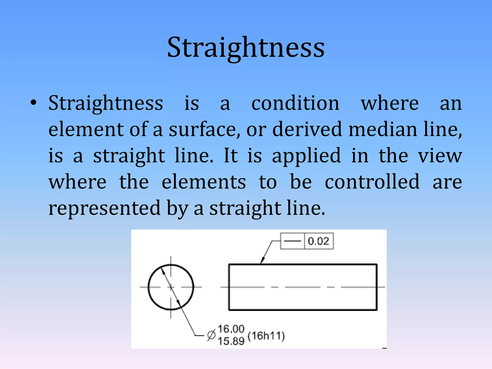
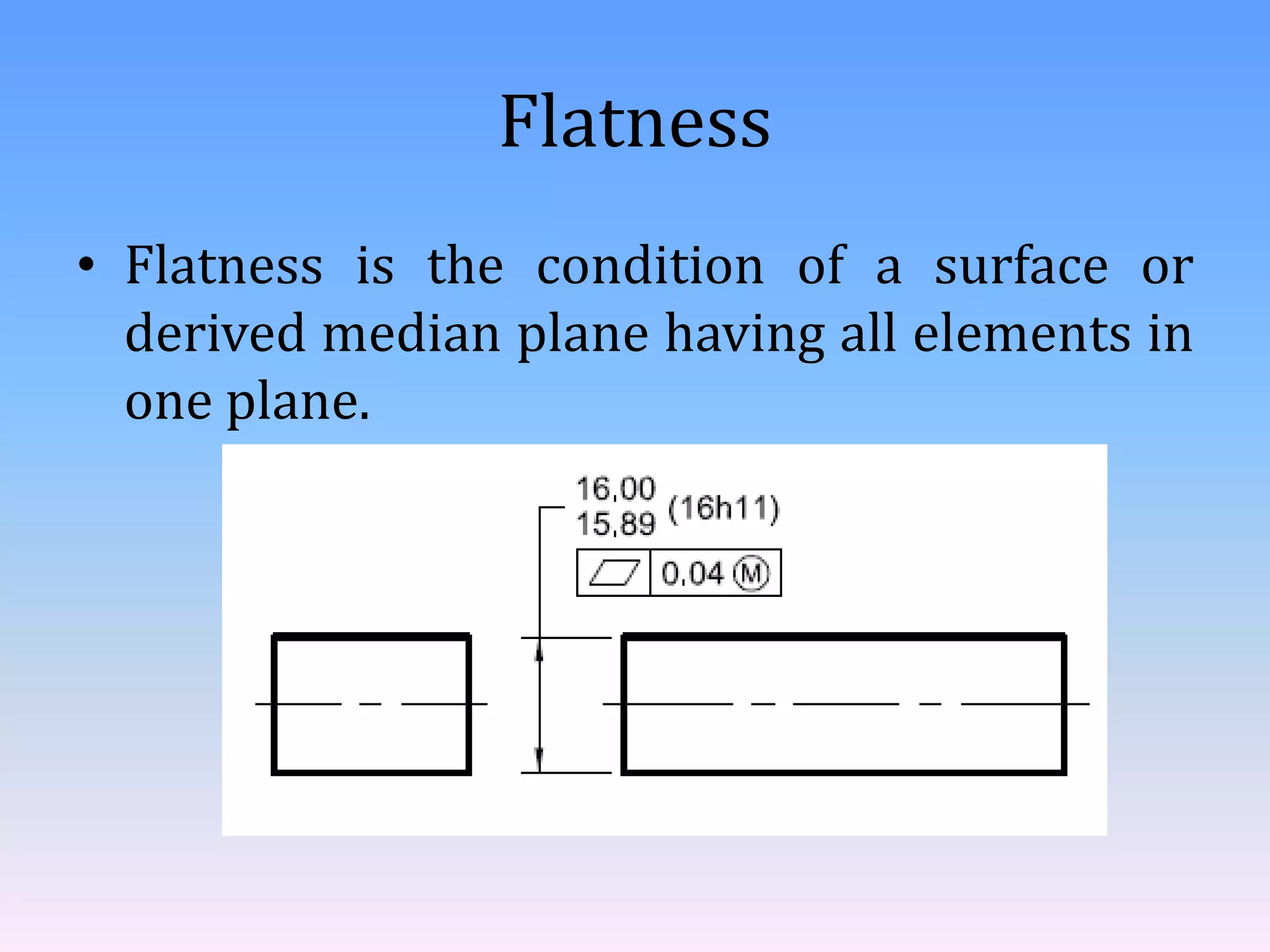
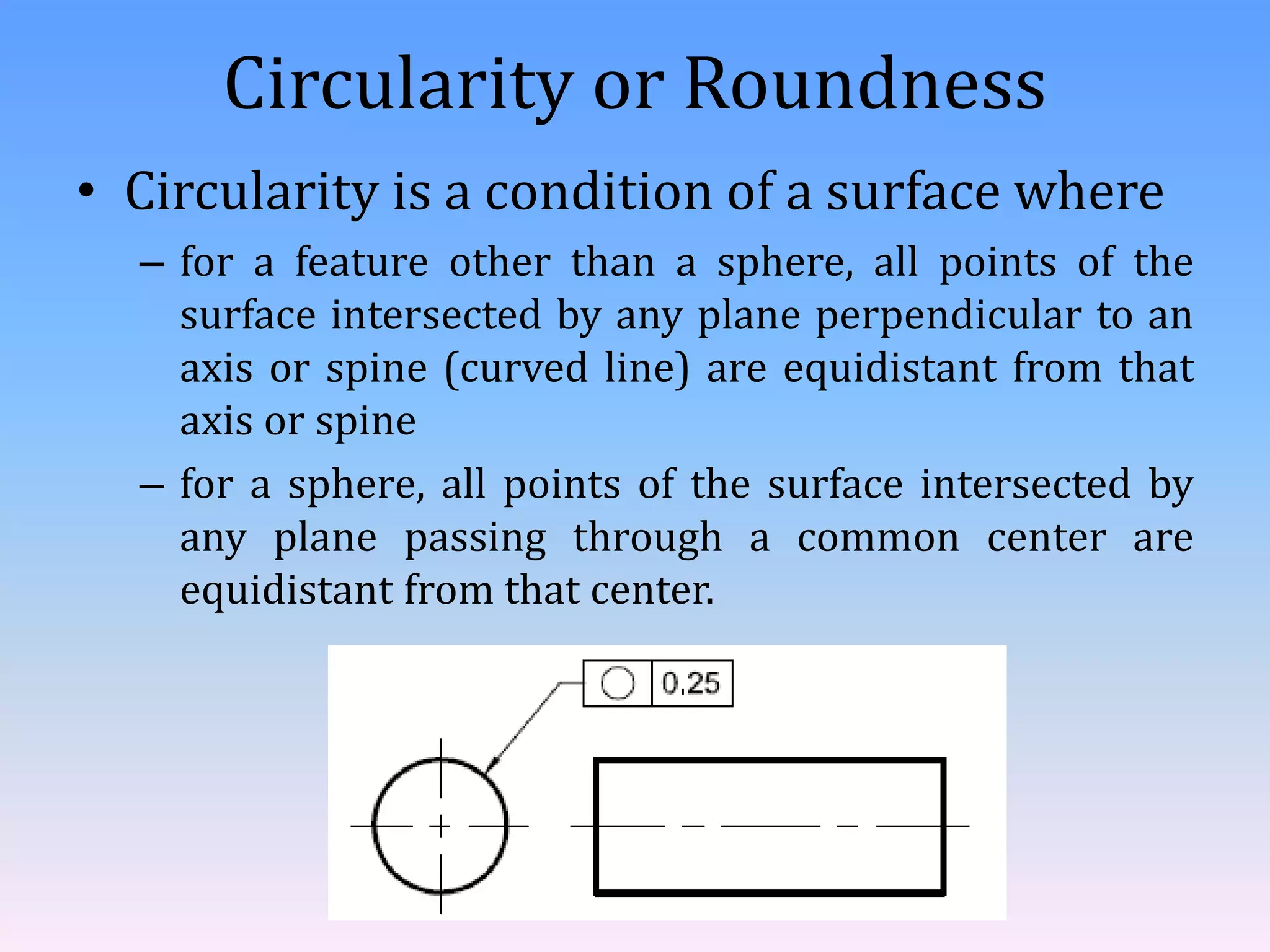
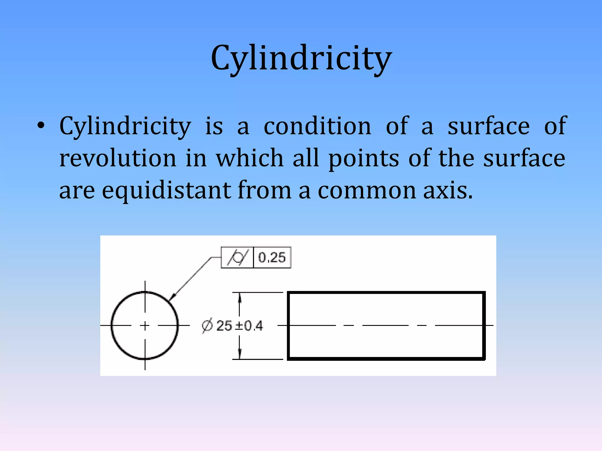
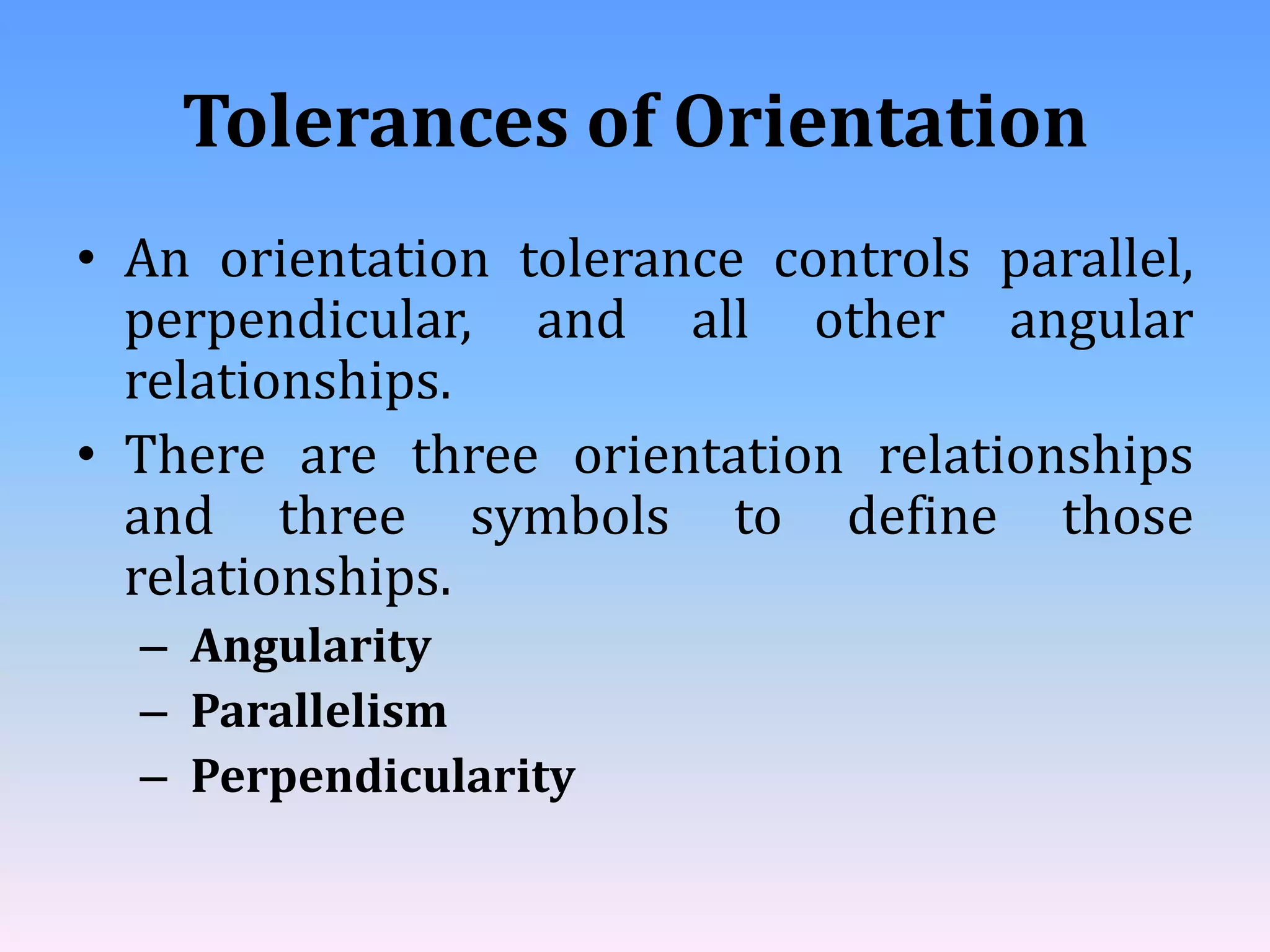
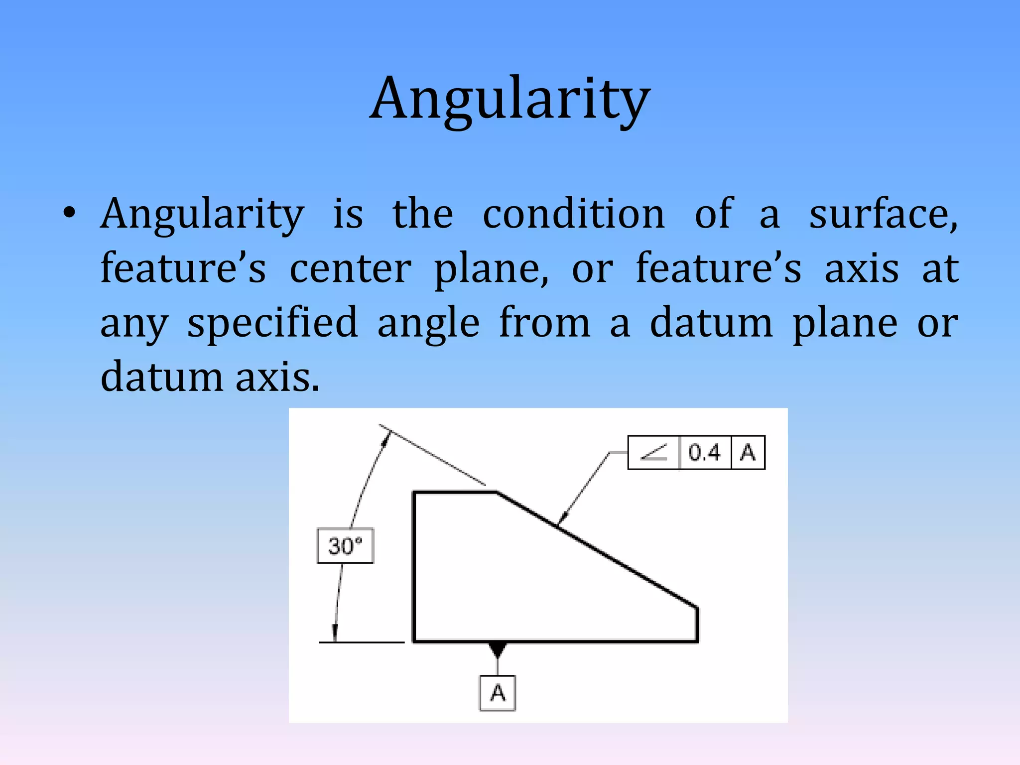
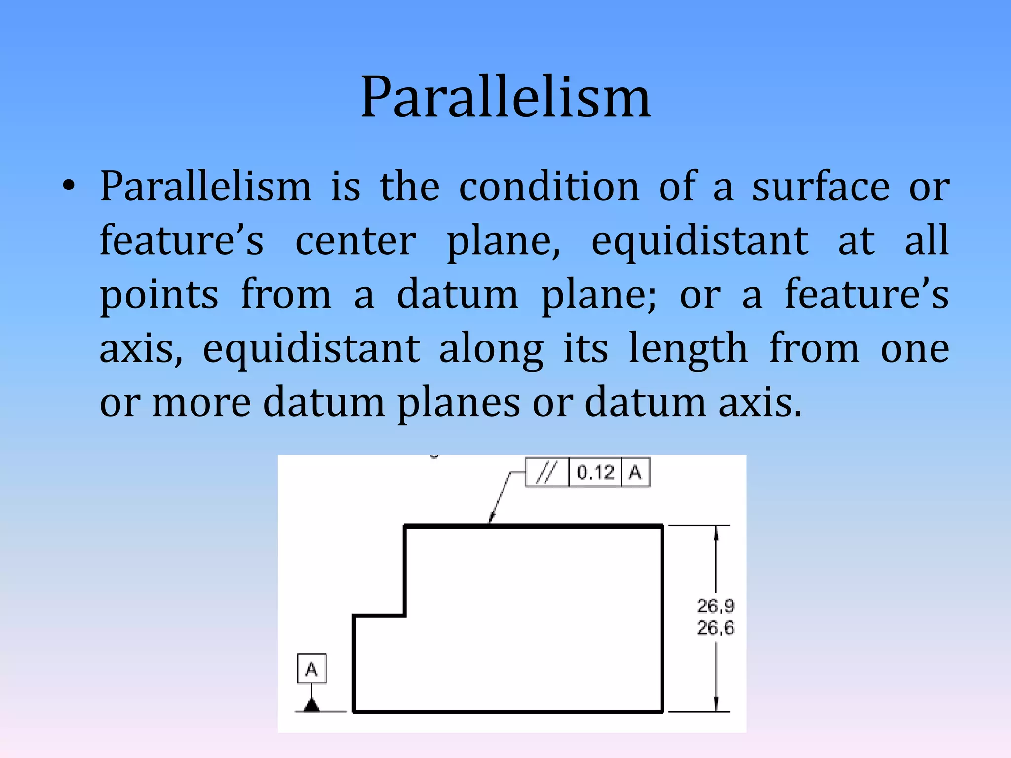
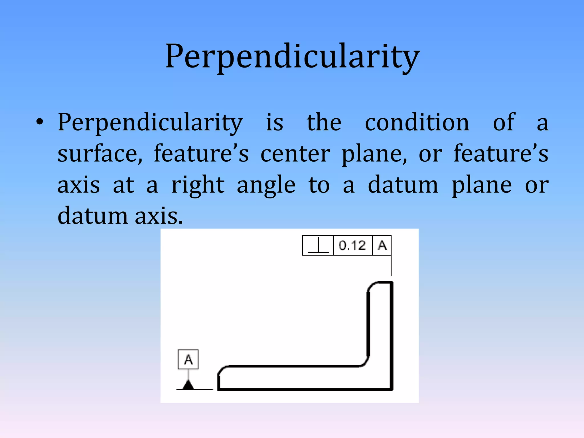
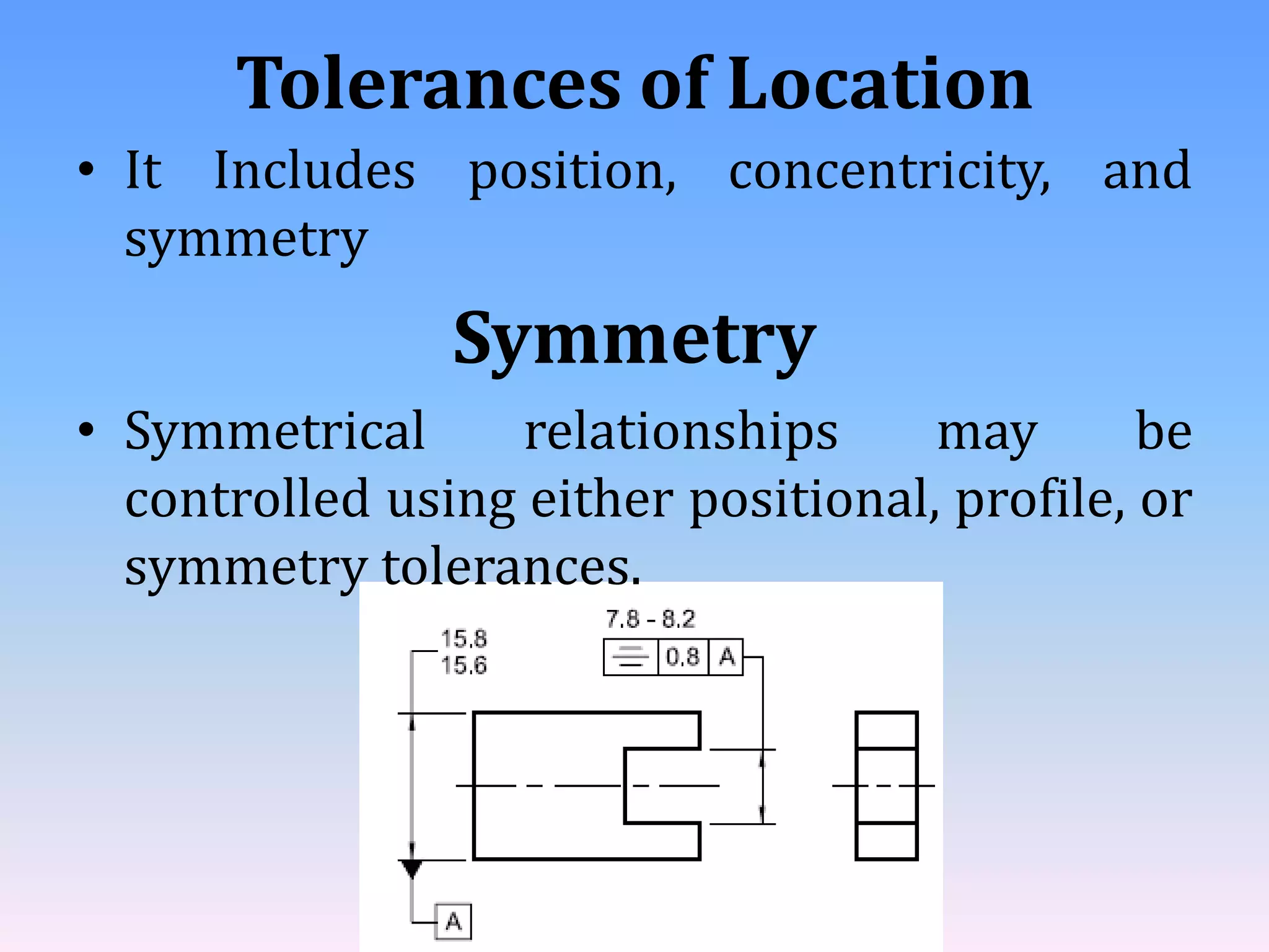
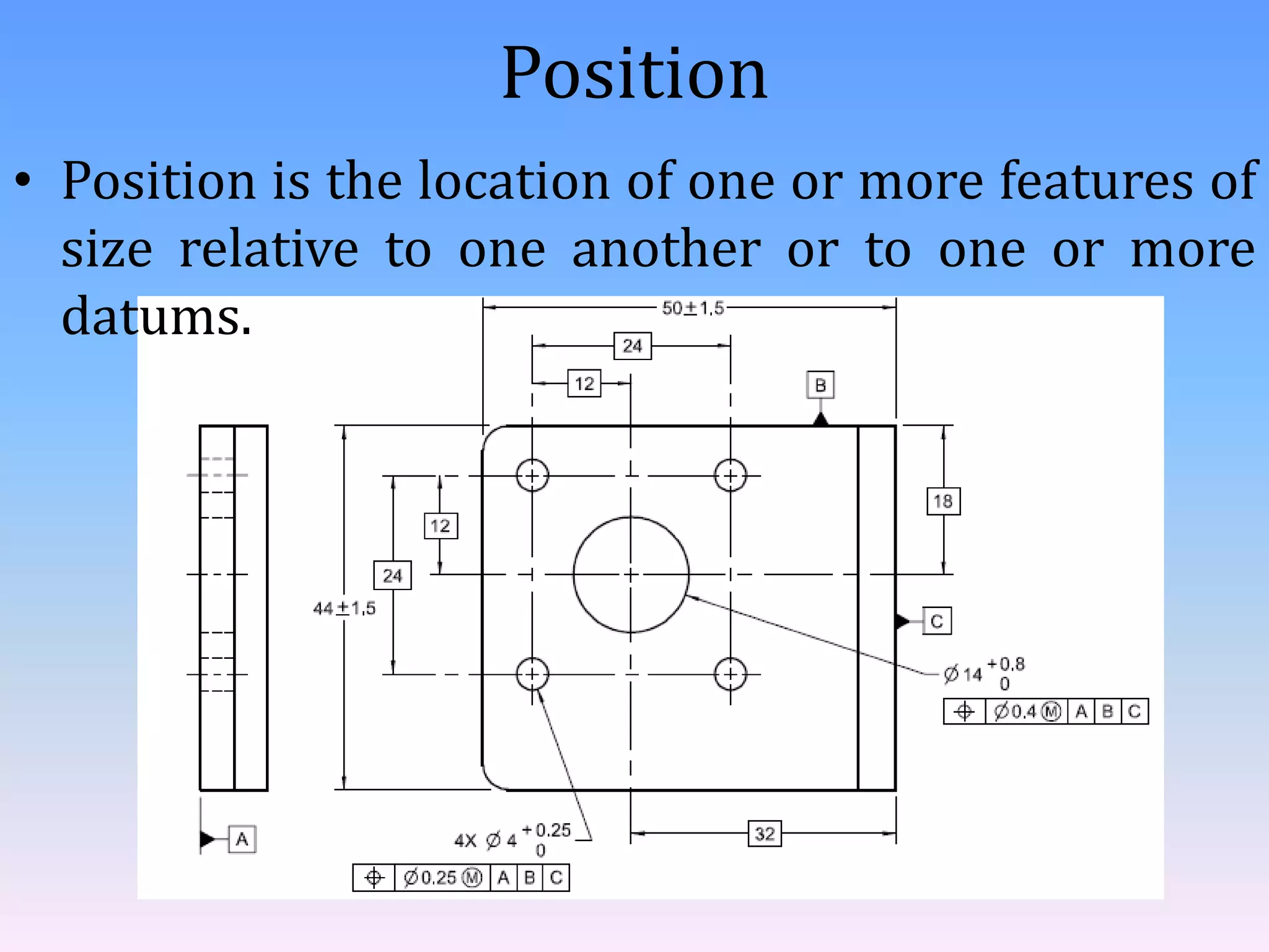
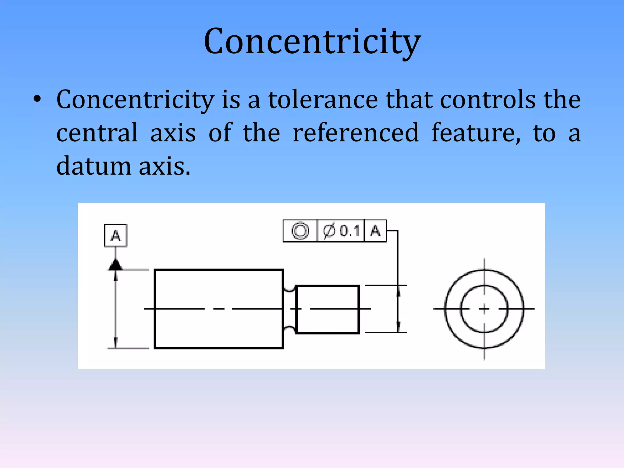
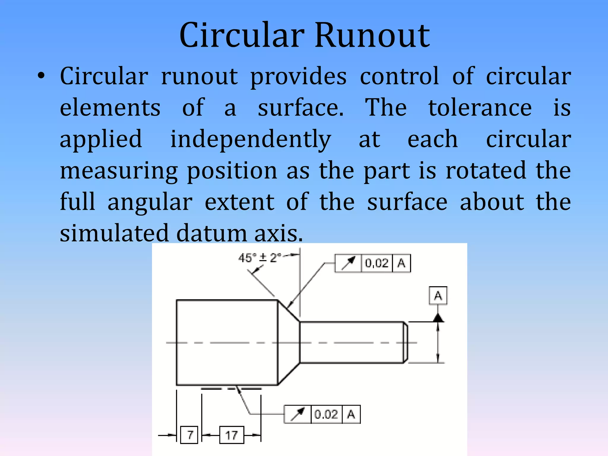
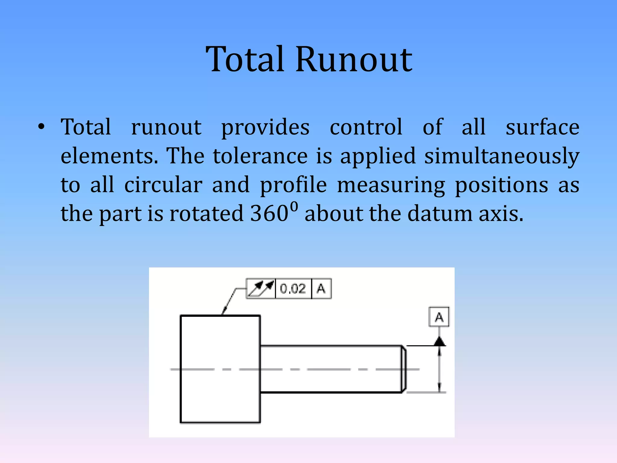
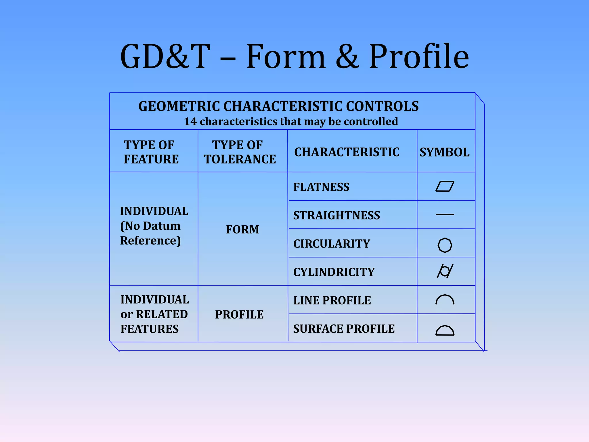
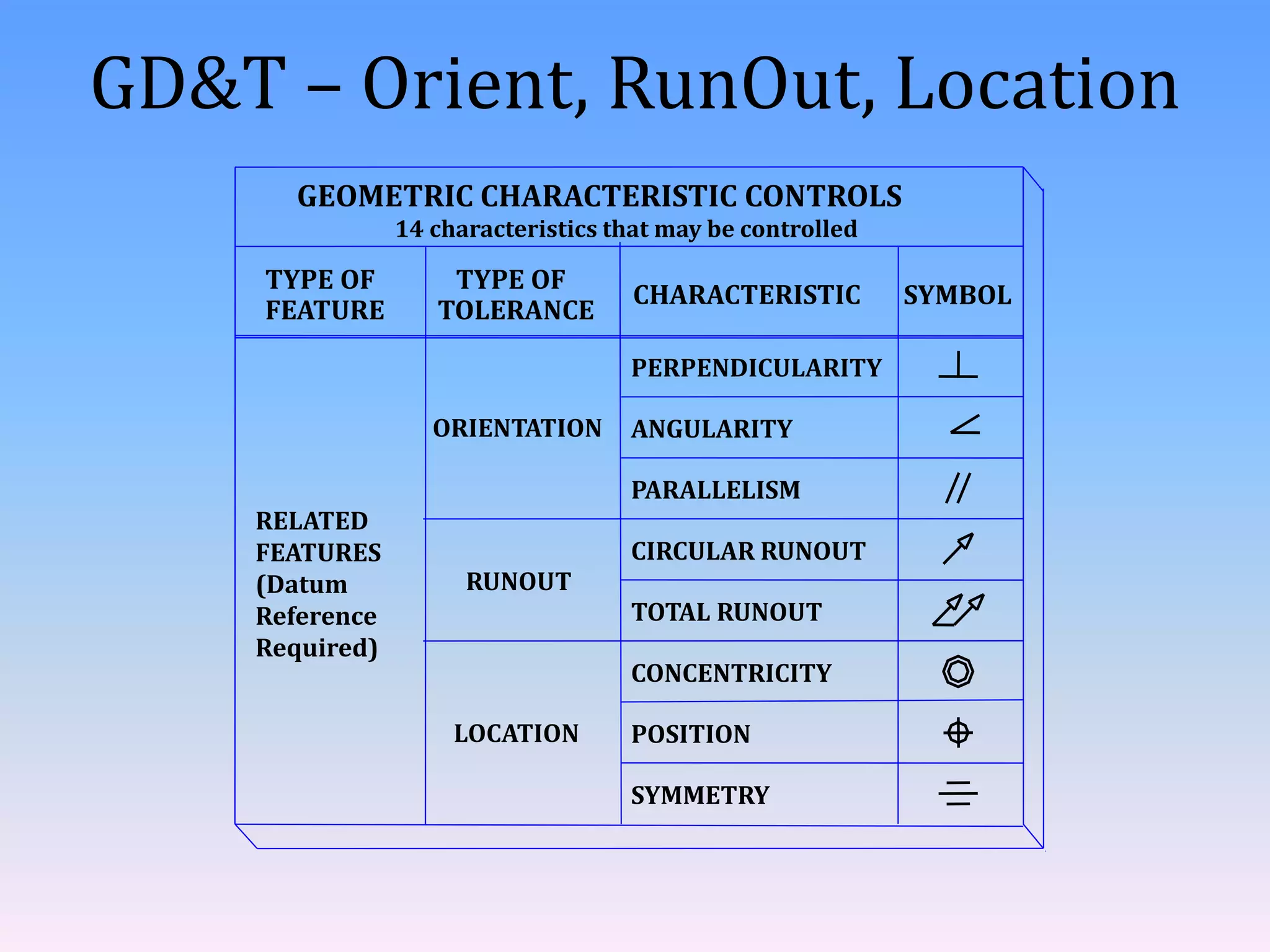
Geometric Dimensioning and
Tolerance
- Harshada Gurav.
Introduction to ASME Y14.5 – 2009
• It is a standard published by American Society of
Mechanical Engineers (ASME) and is considered
the authoritative guideline for the design language
of geometric dimensioning and tolerance (GD&T).
• The International System of Units (SI) is featured
in this Standard
ANSI/ASME Y14.5
 Responsibility for Maintenance of the Standard
Shifted ANSI → ASME after the 1994 Version
Example
Tolerances of Form
• Form tolerances control straightness,
flatness, circularity, and cylindricity.
• Form tolerances are applicable to single
(individual) features, elements of single
features, or features of size.
Straightness
• Straightness is a condition where an
element of a surface, or derived median line,
is a straight line. It is applied in the view
where the elements to be controlled are
represented by a straight line.
Flatness
• Flatness is the condition of a surface or
derived median plane having all elements in
one plane.
Circularity or Roundness
• Circularity is a condition of a surface where
– for a feature other than a sphere, all points of the
surface intersected by any plane perpendicular to an
axis or spine (curved line) are equidistant from that
axis or spine
– for a sphere, all points of the surface intersected by
any plane passing through a common center are
equidistant from that center.
Cylindricity
• Cylindricity is a condition of a surface of
revolution in which all points of the surface
are equidistant from a common axis.
Tolerances of Orientation
• An orientation tolerance controls parallel,
perpendicular, and all other angular
relationships.
• There are three orientation relationships
and three symbols to define those
relationships.
– Angularity
– Parallelism
– Perpendicularity
Angularity
• Angularity is the condition of a surface,
feature’s center plane, or feature’s axis at
any specified angle from a datum plane or
datum axis.
Parallelism
• Parallelism is the condition of a surface or
feature’s center plane, equidistant at all
points from a datum plane; or a feature’s
axis, equidistant along its length from one
or more datum planes or datum axis.
Perpendicularity
• Perpendicularity is the condition of a
surface, feature’s center plane, or feature’s
axis at a right angle to a datum plane or
datum axis.
Tolerances of Location
• It Includes position, concentricity, and
symmetry
Symmetry
• Symmetrical relationships may be
controlled using either positional, profile, or
symmetry tolerances.
Position
• Position is the location of one or more features of
size relative to one another or to one or more
datums.
Concentricity
• Concentricity is a tolerance that controls the
central axis of the referenced feature, to a
datum axis.
Tolerances of Profile
• A profile tolerance may be applied to an
entire part, multiple features, individual
surfaces, or to individual profiles taken at
various cross sections through a part.
• There are two types
– Line profile
– surface profile
Line profile
• Each line element tolerance zone established by
the profile of a line tolerance requirement is two-
dimensional (an area) and the tolerance zone is
normal to the true profile of the feature at each
line element.
surface profile
• The surface profile tolerance is three
dimensional (a volume), extending along the
length and width (or circumference) of the
considered feature or features.
Tolerances of Runout
• Runout is a tolerance used to control the
functional relationship of one or more
features to a datum axis established from a
datum feature specified at RMB (Regardless
of Material Boundary).
• TYPES OF RUNOUT TOLERANCES
– Circular Runout
– Total Runout
Circular Runout
• Circular runout provides control of circular
elements of a surface. The tolerance is
applied independently at each circular
measuring position as the part is rotated the
full angular extent of the surface about the
simulated datum axis.
Total Runout
• Total runout provides control of all surface
elements. The tolerance is applied simultaneously
to all circular and profile measuring positions as
the part is rotated 360⁰ about the datum axis.
GD&T – Form & Profile
INDIVIDUAL
(No Datum
Reference)
INDIVIDUAL
or RELATED
FEATURES
GEOMETRIC CHARACTERISTIC CONTROLS
TYPE OF
FEATURE
TYPE OF
TOLERANCE
CHARACTERISTIC SYMBOL
FLATNESS
STRAIGHTNESS
CIRCULARITY
CYLINDRICITY
LINE PROFILE
SURFACE PROFILE
FORM
PROFILE
14 characteristics that may be controlled
GD&T – Orient, RunOut, Location
RELATED
FEATURES
(Datum
Reference
Required)
GEOMETRIC CHARACTERISTIC CONTROLS
TYPE OF
FEATURE
TYPE OF
TOLERANCE
CHARACTERISTIC SYMBOL
SYMMETRY
PERPENDICULARITY
ANGULARITY
PARALLELISM
CIRCULAR RUNOUT
TOTAL RUNOUT
CONCENTRICITY
POSITION
ORIENTATION
RUNOUT
LOCATION
14 characteristics that may be controlled
Geometric dimensioning and tolerance

Geometric dimensioning and tolerance

  • 1.
  • 2.
    Introduction to ASMEY14.5 – 2009 • It is a standard published by American Society of Mechanical Engineers (ASME) and is considered the authoritative guideline for the design language of geometric dimensioning and tolerance (GD&T). • The International System of Units (SI) is featured in this Standard
  • 3.
    ANSI/ASME Y14.5  Responsibilityfor Maintenance of the Standard Shifted ANSI → ASME after the 1994 Version
  • 4.
  • 5.
    Tolerances of Form •Form tolerances control straightness, flatness, circularity, and cylindricity. • Form tolerances are applicable to single (individual) features, elements of single features, or features of size.
  • 6.
    Straightness • Straightness isa condition where an element of a surface, or derived median line, is a straight line. It is applied in the view where the elements to be controlled are represented by a straight line.
  • 7.
    Flatness • Flatness isthe condition of a surface or derived median plane having all elements in one plane.
  • 8.
    Circularity or Roundness •Circularity is a condition of a surface where – for a feature other than a sphere, all points of the surface intersected by any plane perpendicular to an axis or spine (curved line) are equidistant from that axis or spine – for a sphere, all points of the surface intersected by any plane passing through a common center are equidistant from that center.
  • 9.
    Cylindricity • Cylindricity isa condition of a surface of revolution in which all points of the surface are equidistant from a common axis.
  • 10.
    Tolerances of Orientation •An orientation tolerance controls parallel, perpendicular, and all other angular relationships. • There are three orientation relationships and three symbols to define those relationships. – Angularity – Parallelism – Perpendicularity
  • 11.
    Angularity • Angularity isthe condition of a surface, feature’s center plane, or feature’s axis at any specified angle from a datum plane or datum axis.
  • 12.
    Parallelism • Parallelism isthe condition of a surface or feature’s center plane, equidistant at all points from a datum plane; or a feature’s axis, equidistant along its length from one or more datum planes or datum axis.
  • 13.
    Perpendicularity • Perpendicularity isthe condition of a surface, feature’s center plane, or feature’s axis at a right angle to a datum plane or datum axis.
  • 14.
    Tolerances of Location •It Includes position, concentricity, and symmetry Symmetry • Symmetrical relationships may be controlled using either positional, profile, or symmetry tolerances.
  • 15.
    Position • Position isthe location of one or more features of size relative to one another or to one or more datums.
  • 16.
    Concentricity • Concentricity isa tolerance that controls the central axis of the referenced feature, to a datum axis.
  • 17.
    Tolerances of Profile •A profile tolerance may be applied to an entire part, multiple features, individual surfaces, or to individual profiles taken at various cross sections through a part. • There are two types – Line profile – surface profile
  • 18.
    Line profile • Eachline element tolerance zone established by the profile of a line tolerance requirement is two- dimensional (an area) and the tolerance zone is normal to the true profile of the feature at each line element.
  • 19.
    surface profile • Thesurface profile tolerance is three dimensional (a volume), extending along the length and width (or circumference) of the considered feature or features.
  • 20.
    Tolerances of Runout •Runout is a tolerance used to control the functional relationship of one or more features to a datum axis established from a datum feature specified at RMB (Regardless of Material Boundary). • TYPES OF RUNOUT TOLERANCES – Circular Runout – Total Runout
  • 21.
    Circular Runout • Circularrunout provides control of circular elements of a surface. The tolerance is applied independently at each circular measuring position as the part is rotated the full angular extent of the surface about the simulated datum axis.
  • 22.
    Total Runout • Totalrunout provides control of all surface elements. The tolerance is applied simultaneously to all circular and profile measuring positions as the part is rotated 360⁰ about the datum axis.
  • 23.
    GD&T – Form& Profile INDIVIDUAL (No Datum Reference) INDIVIDUAL or RELATED FEATURES GEOMETRIC CHARACTERISTIC CONTROLS TYPE OF FEATURE TYPE OF TOLERANCE CHARACTERISTIC SYMBOL FLATNESS STRAIGHTNESS CIRCULARITY CYLINDRICITY LINE PROFILE SURFACE PROFILE FORM PROFILE 14 characteristics that may be controlled
  • 24.
    GD&T – Orient,RunOut, Location RELATED FEATURES (Datum Reference Required) GEOMETRIC CHARACTERISTIC CONTROLS TYPE OF FEATURE TYPE OF TOLERANCE CHARACTERISTIC SYMBOL SYMMETRY PERPENDICULARITY ANGULARITY PARALLELISM CIRCULAR RUNOUT TOTAL RUNOUT CONCENTRICITY POSITION ORIENTATION RUNOUT LOCATION 14 characteristics that may be controlled