This presentation gives the information about Screw thread measurements and Gear measurement of the subject: Mechanical measurement and Metrology (10ME32/42) of VTU Syllabus covering unit-4.
This presentation gives the information about Screw thread measurements and Gear measurement of the subject: Mechanical measurement and Metrology (10ME32/42) of VTU Syllabus covering unit-4.
Surface roughness metrology deals with basic terminology of surface,surface roughness indication methods,analysis of surface traces, measurement methods,surface roughness measuring instruments such as Stylus Probe Instrument, Profilometer, Tomlinson Surface Meter ,The Taylor-Hobson Talysurf etc.This is very useful for diploma,degree engineering students of mechanical,production,automobile branch
Coordinate metrology is concerned with the measurement of the actual shape and dimensions of an object and comparing these with the desired shape and dimensions.
In this connection, coordinate metrology consists of the evaluation of the location, orientation, dimensions, and geometry of the part or object.
A Coordinate Measuring Machine (CMM) is an electromechanical system designed to perform coordinate metrology.
Introduction to Mechanical Measurements and Metrology taruian
Introduction to Metrology: Definition, objectives of metrology, Material Standards, Wavelength Standards, Classification of standards, Line and End standards, Calibration of End bars. Numerical examples.
Industrial Training at Shahjalal Fertilizer Company Limited (SFCL)MdTanvirMahtab2
This presentation is about the working procedure of Shahjalal Fertilizer Company Limited (SFCL). A Govt. owned Company of Bangladesh Chemical Industries Corporation under Ministry of Industries.
Cosmetic shop management system project report.pdfKamal Acharya
Buying new cosmetic products is difficult. It can even be scary for those who have sensitive skin and are prone to skin trouble. The information needed to alleviate this problem is on the back of each product, but it's thought to interpret those ingredient lists unless you have a background in chemistry.
Instead of buying and hoping for the best, we can use data science to help us predict which products may be good fits for us. It includes various function programs to do the above mentioned tasks.
Data file handling has been effectively used in the program.
The automated cosmetic shop management system should deal with the automation of general workflow and administration process of the shop. The main processes of the system focus on customer's request where the system is able to search the most appropriate products and deliver it to the customers. It should help the employees to quickly identify the list of cosmetic product that have reached the minimum quantity and also keep a track of expired date for each cosmetic product. It should help the employees to find the rack number in which the product is placed.It is also Faster and more efficient way.
CFD Simulation of By-pass Flow in a HRSG module by R&R Consult.pptxR&R Consult
CFD analysis is incredibly effective at solving mysteries and improving the performance of complex systems!
Here's a great example: At a large natural gas-fired power plant, where they use waste heat to generate steam and energy, they were puzzled that their boiler wasn't producing as much steam as expected.
R&R and Tetra Engineering Group Inc. were asked to solve the issue with reduced steam production.
An inspection had shown that a significant amount of hot flue gas was bypassing the boiler tubes, where the heat was supposed to be transferred.
R&R Consult conducted a CFD analysis, which revealed that 6.3% of the flue gas was bypassing the boiler tubes without transferring heat. The analysis also showed that the flue gas was instead being directed along the sides of the boiler and between the modules that were supposed to capture the heat. This was the cause of the reduced performance.
Based on our results, Tetra Engineering installed covering plates to reduce the bypass flow. This improved the boiler's performance and increased electricity production.
It is always satisfying when we can help solve complex challenges like this. Do your systems also need a check-up or optimization? Give us a call!
Work done in cooperation with James Malloy and David Moelling from Tetra Engineering.
More examples of our work https://www.r-r-consult.dk/en/cases-en/
Immunizing Image Classifiers Against Localized Adversary Attacksgerogepatton
This paper addresses the vulnerability of deep learning models, particularly convolutional neural networks
(CNN)s, to adversarial attacks and presents a proactive training technique designed to counter them. We
introduce a novel volumization algorithm, which transforms 2D images into 3D volumetric representations.
When combined with 3D convolution and deep curriculum learning optimization (CLO), itsignificantly improves
the immunity of models against localized universal attacks by up to 40%. We evaluate our proposed approach
using contemporary CNN architectures and the modified Canadian Institute for Advanced Research (CIFAR-10
and CIFAR-100) and ImageNet Large Scale Visual Recognition Challenge (ILSVRC12) datasets, showcasing
accuracy improvements over previous techniques. The results indicate that the combination of the volumetric
input and curriculum learning holds significant promise for mitigating adversarial attacks without necessitating
adversary training.
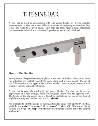
1. THE SINE BAR
A sine bar is used in conjunction with slip gauge blocks for precise angular
measurement. A sine bar is used either to measure an angle very accurately or face
locate any work to a given angle. Sine bars are made from a high chromium
corrosion resistant steel, and is hardened, precision ground, and stabilized.
Figure 1. The Sine Bar
Two cylinders of equal diameter are placed at the ends of the bar. The axes of these
two cylinders are mutually parallel to each other, and are also parallel to, and at
equal distance from, the upper surface of the sine bar. Accuracy up to 0.01mm/m of
length of the sine bar can be obtained.
A sine bar is generally used with slip gauge blocks. The sine bar forms the
hypotenuse of a right triangle, while the slip gauge blocks form the opposite side.
The height of the slip gauge block is found by multiplying the sine of the desired
angle by the length of the sine bar: H = L * sin(θ).
For example, to find the gauge block height for a 13˚ angle with a 5.000″ sine bar,
multiply the sin(13˚) by 5.000″: H = 5.000″ * sin(13˚). Slip gauge blocks
stacked to a height of 1.124″ would then be used elevate the sine bar to the desired
angle of 13˚.
2. SINE BAR PRINCIPLES
The application of trigonometry applies to sine bar usage.
A surface plate, sine bar, and slip gauges are used for the precise formation of
an angle.
It is possible to set up any angle ϴ by using the standard length of side AB, and
calculating the height of side BC using BC = AB * sin(ϴ).
The angle ϴ is given by ϴ = asin(BC/AB).
Figure 1 shows a typical sine bar set up on a surface plate with slip gauge
blocks of the required height BC to form a desired angle ϴ.
Figure 2: Forming an Angle with a Sine Bar and Gauge Blocks
3. WRINGING
The term wringing refers to a condition of intimate and complete contact by tight
adhesion between measuring faces. Wringing is done by hand by sliding and
twisting motions. One gauge is placed perpendicular to other using standard
gauging pressure then a rotary motion is applied until the blocks are lined up. In
this way air is expelled from between the gauge faces causing the blocks to adhere.
This adherence is caused partially by molecular attraction and partially by
atmospheric pressure. Similarly, for separating slip gauges, a combined sliding and
twisting motion should be used.
1. To set an angle on any sine bar, you must first determine the center distance of the
sine bar (C), the angle you wish to set (A) and whether the angle is in degrees-
minutes-seconds or decimal degrees.
2. Next, enter that information in the appropriate input areas below. Use a decimal
point for the separator, whether the angle is in degrees-minutes-seconds or decimal
degrees.
3. Hit the ‘Calculate’ button and then assemble a stack of gauge blocks (G) to equal
the size that is returned. The units of the stack will match the units of the center
distance (i.e., If you enter the center distance as 5 for a 5 inch sine plate, the gage
block stack will also be in inches.).
4. Place these slip gauges blocks under the gauge block roll of the sine device and the
desired angle is set.
5. Tighten the locking mechanism on those devices that have one and you’re ready to
go.
Figure 3: Uses the formula: G = C * Sin(A)
4. If you just want to set an angle with a sine bar and stack of blocks, then take the sine
of the desired angle on your calculator and multiply the result by the distance
between the centers of the cylinders in the sine bar. Assemble a stack of blocks equal
to this value and put it under one of the cylinders.
SINE BAR SET-UP CALCULATION
To calculate the gauge block’s height needed to set-up a sine bar to a specific angle
all you have to do is take the SIN of the angle and multiply it by the sine bar length.
The length of the sine bar is the distance between the centers of the sine bar gauge
pins.
Figure 4. Sine Bar
Example:
Set up a 5.0” sine bar or sine plate to 30°
SIN (30˚) = 0.5000
0.5000 x 5.0″ (sine Bar Length) = 2.5000″
Round 2.5000″ to 4 Decimal Places = 2.5000″ Gage Block Height.
5. Table 1 Common Angles and heights for a 5-inch sine bar:
Angle Height
5° 0.4358″
10° 0.8682″
15° 1.2941″
20° 1.7101″
25° 2.1131″
30° 2.5000″
35° 2.8679″
40° 3.2139″
45° 3.5355″
50° 3.8302″
55° 4.0958″
60° 4.3301″
Types
The simplest type consists of a lapped steel bar, at each end of which is attached an
accurate cylinder, the axis of cylinder being mutually parallel and parallel to the
upper surface of the bar. In the advanced type some holes are drilled in the body of
the bar to reduce the weight and facilitate handling.[1]
Sine centre
A special type of sine bar is sine centre which is used for conical objects having male
and female parts. It cannot measure the angle more than 45 degrees
Sine table
A sine table (or sine plate) is a large and wide sine bar, typically equipped with a
mechanism for locking it in place after positioning, which is used to hold workpieces
during operations.
6. Compound sine table
It is used to measure compound angles of large workpiece. In this case, two sine
tables are mounted one over the other at right angles. The tables can be twisted to
get the required alignment.
SINE BAR USAGE
To measure a known angle or locate any work to a given angle:
1. Always use a perfectly flat and clean surface plate.
2. Place one roller on the surface plate and the other roller on the slip gauge block
stack of height H.
3. Let the sine bar be set to an angle ϴ.
4. Then sin(ϴ) = H/L, where L is the distance between the center.
5. Thus knowing ϴ, H can be found and any work can be set out at this angle as
the top face of the sine bar is inclined at angle ϴ to the surface plate.
6. For better result both rollers must placed on slip gauge block of height H1 and
H2 respectively.