Download as PDF, PPTX
![Proportional Control Mode:
Process Instrumentation and Control (ICE 401)
Dr. S.Meenatchisundaram, MIT, Manipal, Aug – Nov 2015
Solution:
Given data:
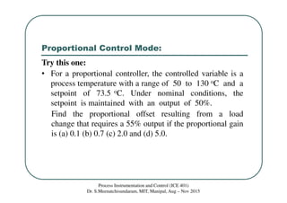
Temperature Range = 50 to 130 oC
Setpoint = 73.5 oC
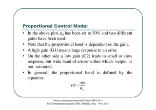
P0 = 50%
P = 55%
ep = ?
Offset error = ? for Kp = 0.1, 0.7, 2.0 & 5.0
For proportional controller: P = Kpep + P0
ep = [P - P0] / Kp = [55 – 50] / Kp = 5 / Kp %](https://image.slidesharecdn.com/class16-floatingandproportionalcontrolmode-150910092807-lva1-app6891/85/Class-16-floating-and-proportional-control-mode-17-320.jpg)
![Proportional Control Mode:
Process Instrumentation and Control (ICE 401)
Dr. S.Meenatchisundaram, MIT, Manipal, Aug – Nov 2015
Solution:
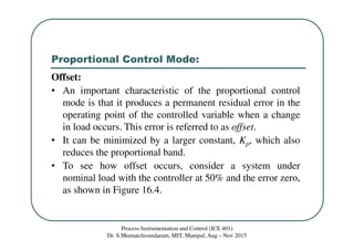
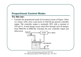
(a) when Kp = 0.1 Offset error, ep = 5/0.1 = 50%
(b) when Kp = 0.7 Offset error, ep = 5/0.7 = 7.1%
(c) when Kp = 2.0 Offset error, ep = 5/2.0 = 2.5%
(d) when Kp = 5.0 Offset error, ep = 5/5.0 = 1%
[It can be observed from the results that as proportional gain
Kp increases the offset error decreases.]](https://image.slidesharecdn.com/class16-floatingandproportionalcontrolmode-150910092807-lva1-app6891/85/Class-16-floating-and-proportional-control-mode-18-320.jpg)

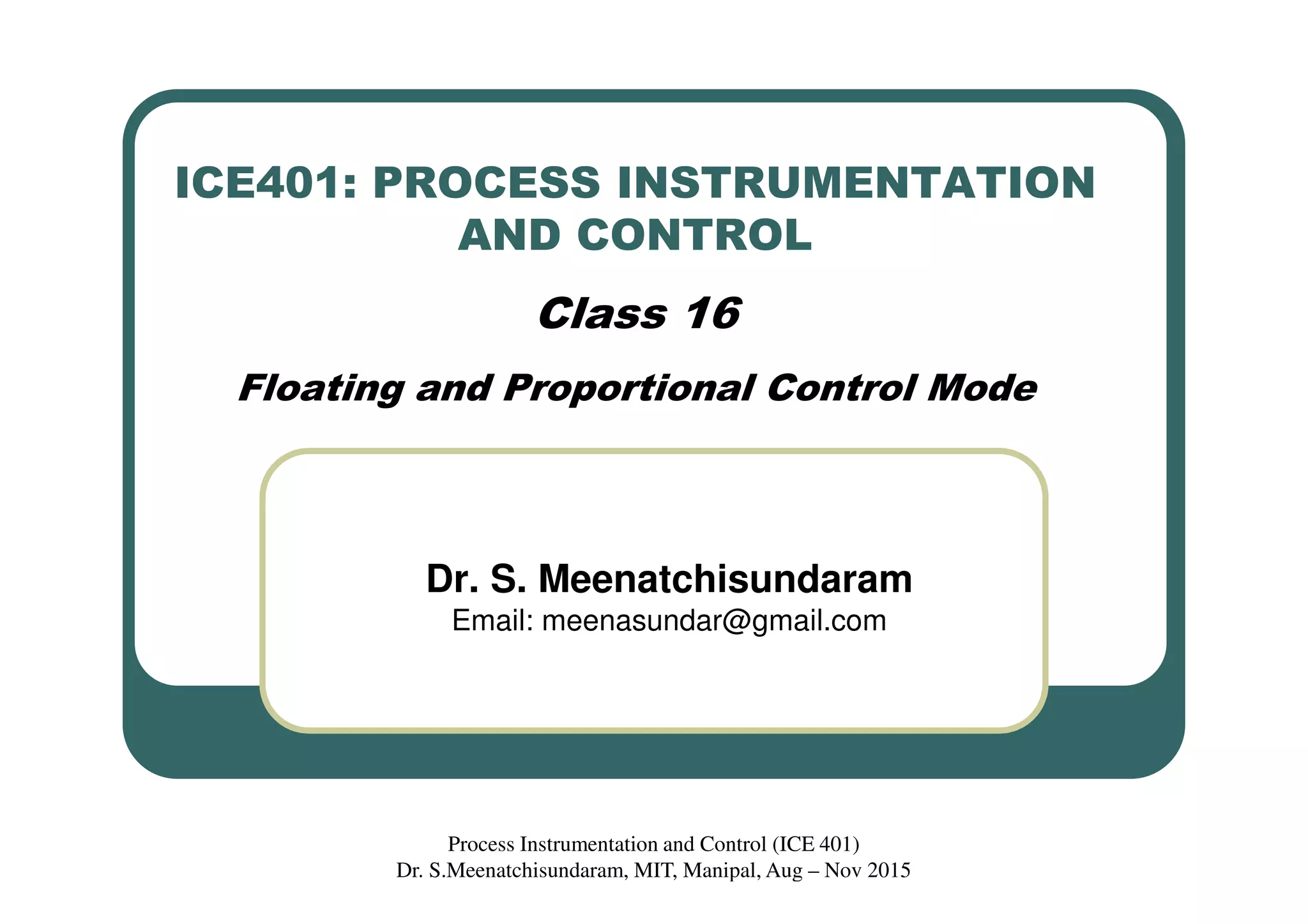
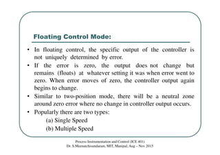
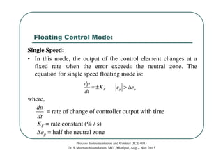
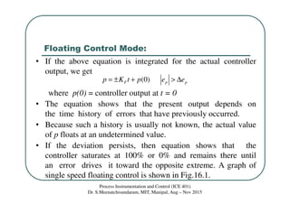
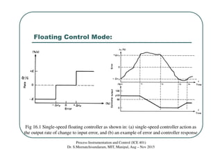
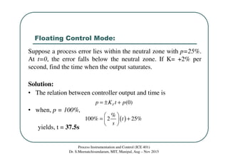
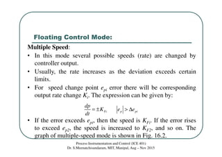
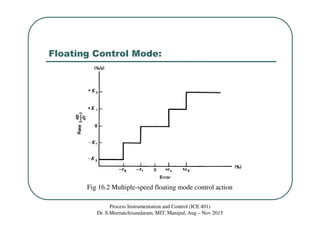
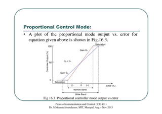
This document discusses floating and proportional control modes. It describes floating control as having a neutral zone where the controller output does not change with error. There are single-speed and multiple-speed floating modes. Proportional control provides a linear relationship between controller output and error over the proportional band. Proportional control results in an offset error due to its inability to achieve a new zero-error output with a load change. Examples are provided to illustrate concepts.


![[Deck] What's New in Spark-Iceberg Integration via DSV2.pptx](https://cdn.slidesharecdn.com/ss_thumbnails/deckwhatsnewinspark-icebergintegrationviadsv2-260210005337-25955b12-thumbnail.jpg?width=640&height=640&fit=bounds)


