2
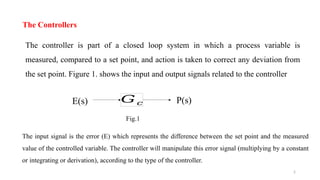
The controller ispart of a closed loop system in which a process variable is
measured, compared to a set point, and action is taken to correct any deviation from
the set point. Figure 1. shows the input and output signals related to the controller
The Controllers
𝐺𝑐
E(s) P(s)
Fig.1
The input signal is the error (E) which represents the difference between the set point and the measured
value of the controlled variable. The controller will manipulate this error signal (multiplying by a constant
or integrating or derivation), according to the type of the controller.
3.
3
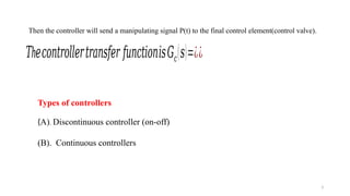
Then the controllerwill send a manipulating signal P(t) to the final control element(control valve).
h
𝑇 𝑒𝑐𝑜𝑛𝑡𝑟𝑜𝑙𝑙𝑒𝑟𝑡𝑟𝑎𝑛𝑠𝑓𝑒𝑟 𝑓𝑢𝑛𝑐𝑡𝑖𝑜𝑛𝑖𝑠𝐺𝑐(𝑠)=¿¿
Types of controllers
(A). Discontinuous controller (on-off)
(B). Continuous controllers
4.
4
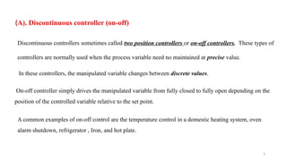
(A). Discontinuous controller(on-off)
Discontinuous controllers sometimes called two position controllers or on-off controllers. These types of
controllers are normally used when the process variable need no maintained at precise value.
In these controllers, the manipulated variable changes between discrete values.
On-off controller simply drives the manipulated variable from fully closed to fully open depending on the
position of the controlled variable relative to the set point.
A common examples of on-off control are the temperature control in a domestic heating system, oven
alarm shutdown, refrigerator , Iron, and hot plate.
5.
5
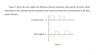
Figure 2 showsthe error signal, the difference between measured value and the set point, which
transmitted to the controller and the controller action which exit from the on-off controller to the final
control element.
Controller action
Error signal 0
0
Figure 2
6.
6
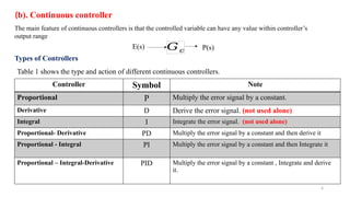
(b). Continuous controller
Themain feature of continuous controllers is that the controlled variable can have any value within controller’s
output range
Types of Controllers
Table 1 shows the type and action of different continuous controllers.
Controller Symbol Note
Proportional P Multiply the error signal by a constant.
Derivative D Derive the error signal. (not used alone)
Integral I Integrate the error signal. (not used alone)
Proportional- Derivative PD Multiply the error signal by a constant and then derive it
Proportional - Integral PI Multiply the error signal by a constant and then Integrate it
Proportional – Integral-Derivative PID Multiply the error signal by a constant , Integrate and derive
it.
𝐺𝑐
E(s) P(s)
7.
7
1- Proportional controller(P)
2- Proportional –Derivative controller(PD)
3-Proportional- integral controller (PI)
4- Proportional-Derivative-Integral controller (PID)
Practically, the controllers can be classified into four types according to their actions:
8.
8
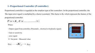
1- Proportional Controller(P controller)
Proportional controller is regarded as the simplest type of the controllers. In the proportional controller, the
The input error signal is multiplied by a factor (constant). This factor is Kc which represent the feature of the
proportional controller.
𝑃 (𝑠)=𝐾 𝑐 𝐸 (𝑠) …………..(1)
𝐾 𝑐
E(s) P(s)
Where:
: Output signal from controller, (Pneumatic , electrical or hydraulic signal).
: Gain or sensitivity
: error signal.
E= Set point – Measured value.
9.
9
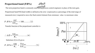
Proportional band (P.B%)
Theterm proportion band is commonly used among process control engineers in place of the term gain.
Proportional band P.B (band width) is defined as the error (expressed as a percentage of the total range of
measured error ) required to move the final control element from minimum value to maximum value
𝑃𝑠𝑠
𝑃𝑟𝑒𝑠𝑠𝑢𝑟𝑒,𝑃
𝐸𝑟𝑟𝑜𝑟,𝐸
0
100%
K c
100%
0 Δ 𝐸
max
max
P.B %=
∆ E
∆ Emax
∗100………(2)
النطاق
التناسبي
Transfer function of the proportional controller is
∴∆ 𝐸=
∆ 𝑝𝑚𝑎𝑥
𝐾𝑐
…………(4)
Substitute (4) in (2) gives
P . B %=
100
K c
∗
∆ pmax
∆ Emax
…………(5)
10.
10
If and aretaken as percentage of the total change then
= =1
Equation (5) becomes
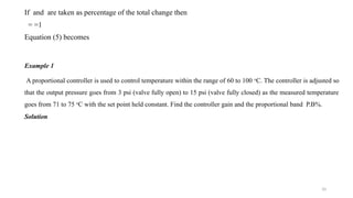
Example 1
A proportional controller is used to control temperature within the range of 60 to 100 o
C. The controller is adjusted so
that the output pressure goes from 3 psi (valve fully open) to 15 psi (valve fully closed) as the measured temperature
goes from 71 to 75 o
C with the set point held constant. Find the controller gain and the proportional band P.B%.
Solution
11.
11
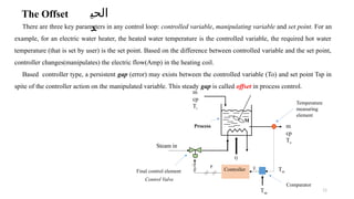
The Offset
There arethree key parameters in any control loop: controlled variable, manipulating variable and set point. For an
example, for an electric water heater, the heated water temperature is the controlled variable, the required hot water
temperature (that is set by user) is the set point. Based on the difference between controlled variable and the set point,
controller changes(manipulates) the electric flow(Amp) in the heating coil.
Based controller type, a persistent gap (error) may exists between the controlled variable (To) and set point Tsp in
spite of the controller action on the manipulated variable. This steady gap is called offset in process control.
m
cp
Ti
Steam in
m
cp
To
M
Q
Tm
Tsp
E
Comparator
Process
Final control element
Temperature
measuring
element
Controller
Control Valve
P
الحي
د
12.
12
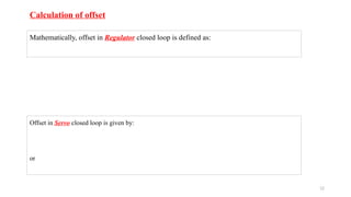
Mathematically, offset inRegulator closed loop is defined as:
Offset in Servo closed loop is given by:
or
Calculation of offset
13.
13
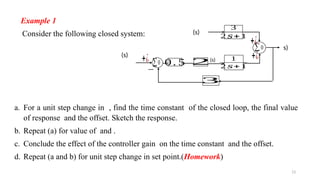
Example 1
Consider thefollowing closed system:
∑0
(s)
(s) 1
2 𝑠+ 1
3
2 𝑠+ 1
s)
+¿
+¿
∑0
(s)
−
+¿ 0 . 5 2
3
a. For a unit step change in , find the time constant of the closed loop, the final value
of response and the offset. Sketch the response.
b. Repeat (a) for value of and .
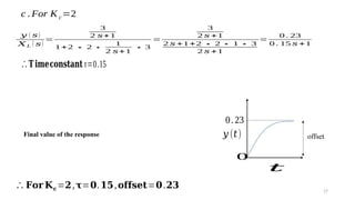
c. Conclude the effect of the controller gain on the time constant and the offset.
d. Repeat (a and b) for unit step change in set point.(Homework)
14.
14
Solution
a. Unit stepchange in , that means the loop is regulator.
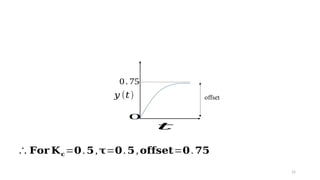
∴𝐓𝐢𝐦𝐞𝐜𝐨𝐧𝐬𝐭𝐚𝐧𝐭 τ=0.5
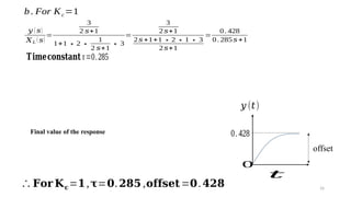
Final value of the response
𝑦 (∞)=0.75
18
c. For thethree values of controller gain Kc, the values of and offset are given in Table 2
0.5 0.5 0.75
1 0.285 0.428
2 0.15 0.28
Table 2
From Table 2, we can conclude that:
for faster response]
for lower value of offset]

![18
c. For the three values of controller gain Kc, the values of and offset are given in Table 2
0.5 0.5 0.75
1 0.285 0.428
2 0.15 0.28
Table 2
From Table 2, we can conclude that:
for faster response]
for lower value of offset]](https://image.slidesharecdn.com/1695199386-250708062004-9d629947/85/proportional-integrator-derivative-controller-pptx-18-320.jpg)