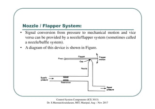
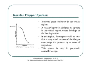
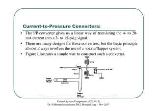
ICE401: PROCESS INSTRUMENTATION
AND CONTROL
Class 22: Flapper Nozzle & I/P Converter
Dr. S. Meenatchisundaram
Email: meenasundar@gmail.com
Control System Components (ICE 3015)
Dr. S.Meenatchisundaram, MIT, Manipal, Aug – Nov 2017
Nozzle / Flapper System:
• Signal conversion from pressure to mechanical motion and vice
versa can be provided by a nozzle/flapper system (sometimes called
a nozzle/baffle system).
• A diagram of this device is shown in Figure.
Control System Components (ICE 3015)
Dr. S.Meenatchisundaram, MIT, Manipal, Aug – Nov 2017
Nozzle / Flapper System:
• A regulated supply of pressure, usually over 20 psig, provides a
source of air through the restriction.
• The nozzle is open at the end where the gap exists between the
nozzle and flapper, and air escapes in this region.
• If the flapper moves down and closes off the nozzle opening so that
no air leaks, the signal pressure will rise to the supply pressure.
• As the flapper moves away, the signal pressure will drop because of
the leaking gas.
• Finally, when the flapper is far away, the pressure will stabilize at
some value determined by the maximum leak through the nozzle.
• Figure shows the relationship between signal pressure and gap
distance.
Control System Components (ICE 3015)
Dr. S.Meenatchisundaram, MIT, Manipal, Aug – Nov 2017
Nozzle / Flapper System:
• Note the great sensitivity in the central
region.
• A nozzle/flapper is designed to operate
in the central region, where the slope of
the line is greatest.
• In this region, the response will be such
that a very small motion of the flapper
can change the pressure by an order of
magnitude.
• This system is used in pneumatic
controller design.
Control System Components (ICE 3015)
Dr. S.Meenatchisundaram, MIT, Manipal, Aug – Nov 2017
Current-to-Pressure Converters:
• The I/P converter gives us a linear way of translating the 4- to 20-
mA current into a 3- to 15-psig signal.
• There are many designs for these converters, but the basic principle
almost always involves the use of a nozzle/flapper system.
• Figure illustrates a simple way to construct such a converter.
Control System Components (ICE 3015)
Dr. S.Meenatchisundaram, MIT, Manipal, Aug – Nov 2017
References:
• Process Control Instrumentation Technology, by Curtis D.
Johnson, Eighth Edition, Pearson Education Limited.
Process Instrumentation and Control (ICE 401)
Dr. S.Meenatchisundaram, MIT, Manipal, Aug – Nov 2015

Lecture 22 flapper nozzle & ip converter

  • 1.
    ICE401: PROCESS INSTRUMENTATION ANDCONTROL Class 22: Flapper Nozzle & I/P Converter Dr. S. Meenatchisundaram Email: meenasundar@gmail.com Control System Components (ICE 3015) Dr. S.Meenatchisundaram, MIT, Manipal, Aug – Nov 2017
  • 2.
    Nozzle / FlapperSystem: • Signal conversion from pressure to mechanical motion and vice versa can be provided by a nozzle/flapper system (sometimes called a nozzle/baffle system). • A diagram of this device is shown in Figure. Control System Components (ICE 3015) Dr. S.Meenatchisundaram, MIT, Manipal, Aug – Nov 2017
  • 3.
    Nozzle / FlapperSystem: • A regulated supply of pressure, usually over 20 psig, provides a source of air through the restriction. • The nozzle is open at the end where the gap exists between the nozzle and flapper, and air escapes in this region. • If the flapper moves down and closes off the nozzle opening so that no air leaks, the signal pressure will rise to the supply pressure. • As the flapper moves away, the signal pressure will drop because of the leaking gas. • Finally, when the flapper is far away, the pressure will stabilize at some value determined by the maximum leak through the nozzle. • Figure shows the relationship between signal pressure and gap distance. Control System Components (ICE 3015) Dr. S.Meenatchisundaram, MIT, Manipal, Aug – Nov 2017
  • 4.
    Nozzle / FlapperSystem: • Note the great sensitivity in the central region. • A nozzle/flapper is designed to operate in the central region, where the slope of the line is greatest. • In this region, the response will be such that a very small motion of the flapper can change the pressure by an order of magnitude. • This system is used in pneumatic controller design. Control System Components (ICE 3015) Dr. S.Meenatchisundaram, MIT, Manipal, Aug – Nov 2017
  • 5.
    Current-to-Pressure Converters: • TheI/P converter gives us a linear way of translating the 4- to 20- mA current into a 3- to 15-psig signal. • There are many designs for these converters, but the basic principle almost always involves the use of a nozzle/flapper system. • Figure illustrates a simple way to construct such a converter. Control System Components (ICE 3015) Dr. S.Meenatchisundaram, MIT, Manipal, Aug – Nov 2017
  • 6.
    References: • Process ControlInstrumentation Technology, by Curtis D. Johnson, Eighth Edition, Pearson Education Limited. Process Instrumentation and Control (ICE 401) Dr. S.Meenatchisundaram, MIT, Manipal, Aug – Nov 2015