Downloaded 30 times

![25
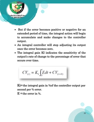
Ki = (d CV / dt) /E
[Ki] = (% /s) /%
Large Ki Small Ki.
Ki 1 is more sensitivity than Small Ki 2.](https://image.slidesharecdn.com/myprocesscontrol1-210809055918/85/Types-of-Controllers-PID-PD-I-PD-25-320.jpg)
![37
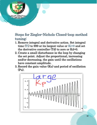
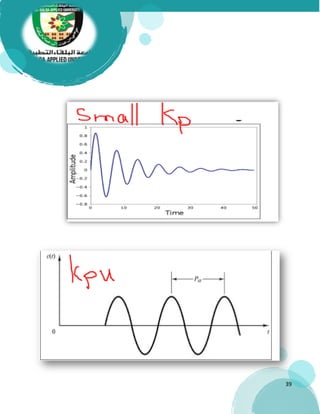
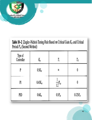
Ziegler-Nichols Closed-loop method
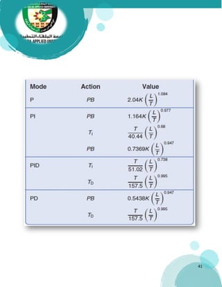
Ziegler-Nichols Closed-loop method is used to obtain the
controller constants [KP, KI (or TI), and KD (or TD)] in a
system with feedback.
It was the first proper algorithmic method for tuning
the PID controllers. It is not widely used today because
closed-loop behavior tends to be oscillatory and
sensitive to uncertainty.
The main objective of the Ziegler-Nichols closed-loop
method is to find the value of the proportional-only
gain that causes the control loop to oscillate
indefinitely at a constant amplitude.
This gain, which causes steady-state oscillations, is
called the ultimate proportional gain (KPU).
(TU) the ultimate period is the time required to
complete one full oscillation once the response begins to
oscillate at a constant amplitude.
Their methods were used for non-first order plus dead
time situations, and involved intense manual
calculations.](https://image.slidesharecdn.com/myprocesscontrol1-210809055918/85/Types-of-Controllers-PID-PD-I-PD-37-320.jpg)
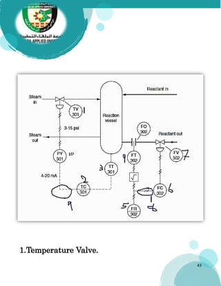
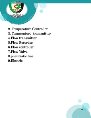

The document outlines the fundamentals of control systems and their types, including open-loop and closed-loop systems, as well as various controller types such as proportional, integral, and derivative controllers. It discusses the importance of process control in optimizing operations, highlighting the role of controllers in regulating process variables and improving system performance. Additionally, it covers tuning methods like the Ziegler-Nichols method for establishing controller constants and the importance of proper instrumentation symbols in control systems.