Download as PDF, PPTX
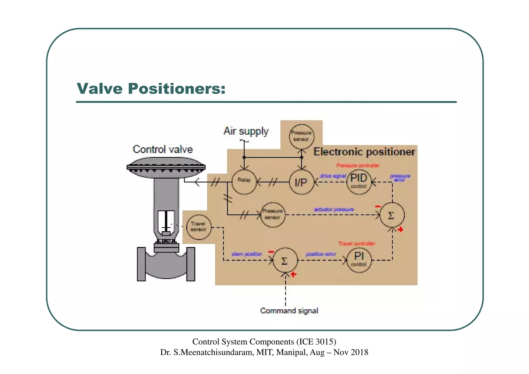
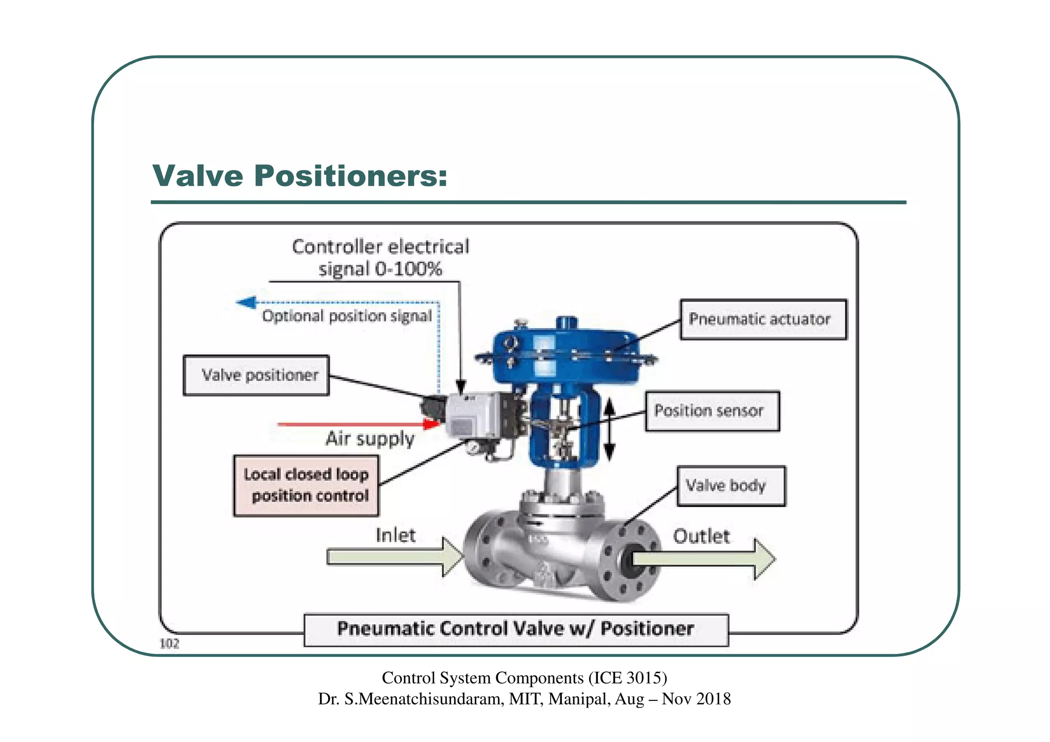
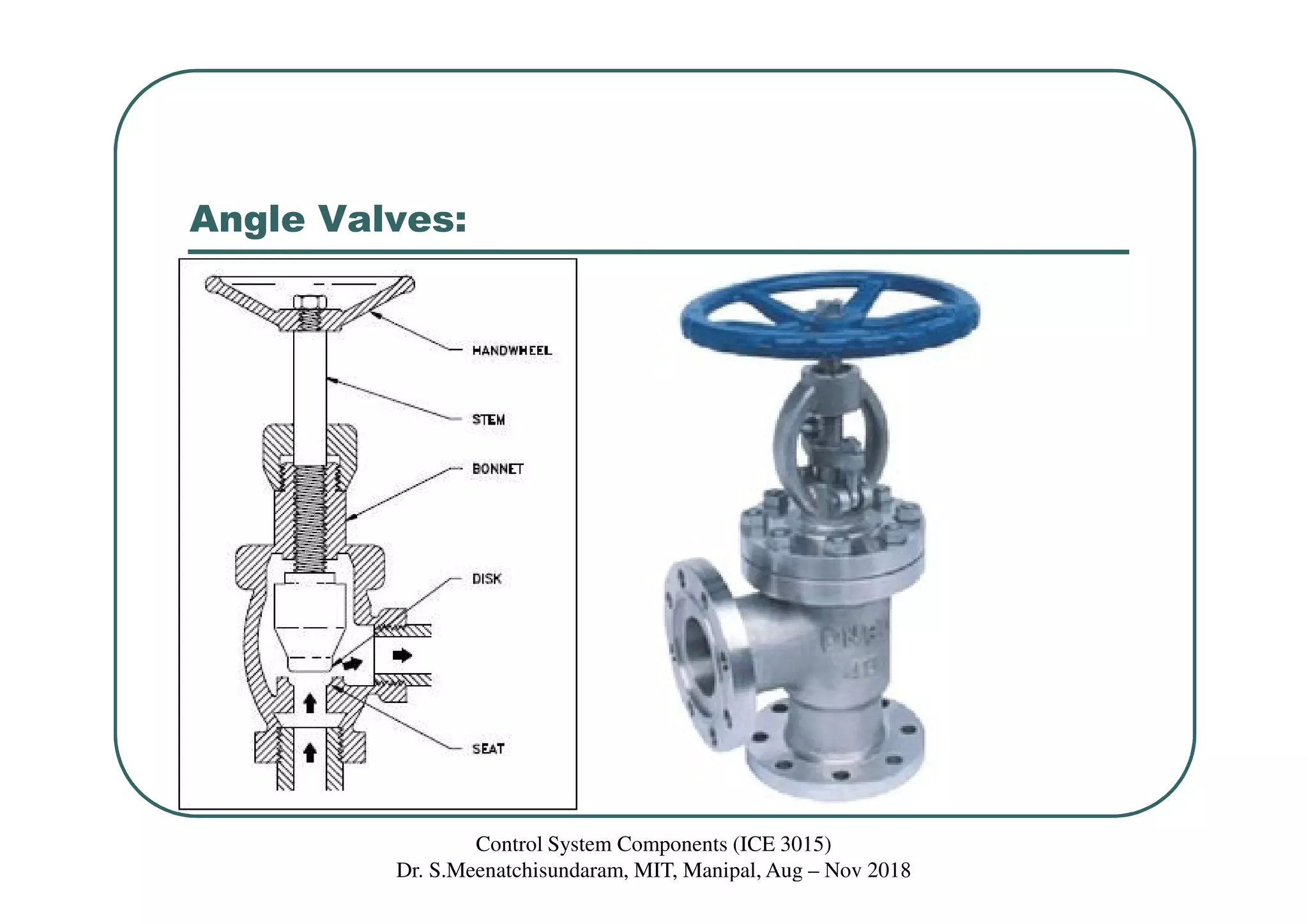
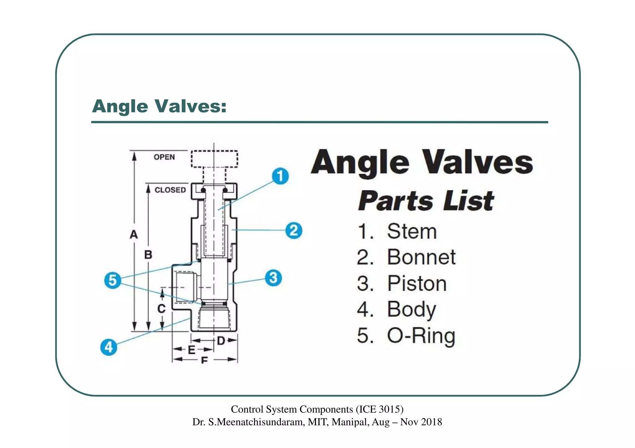
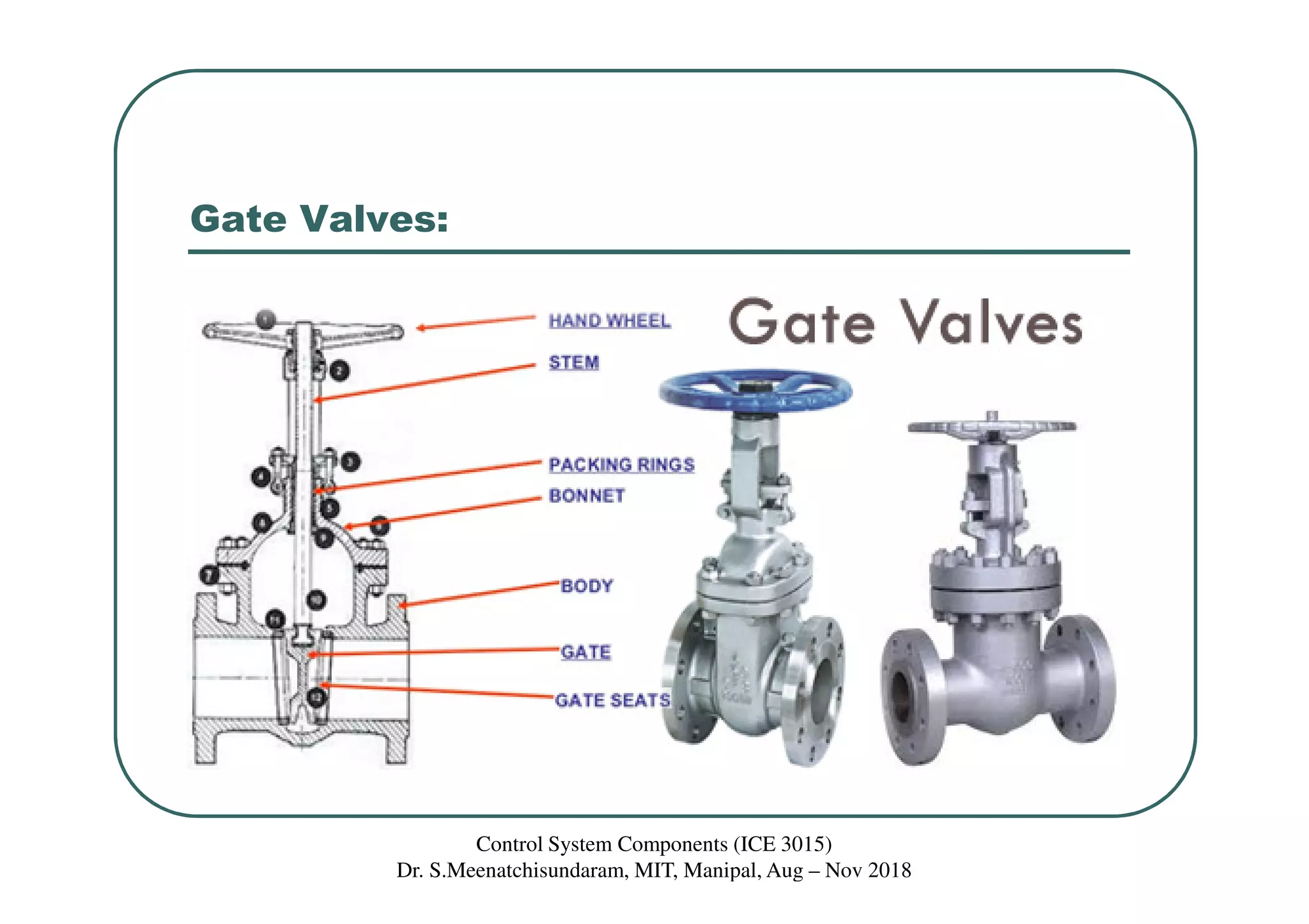
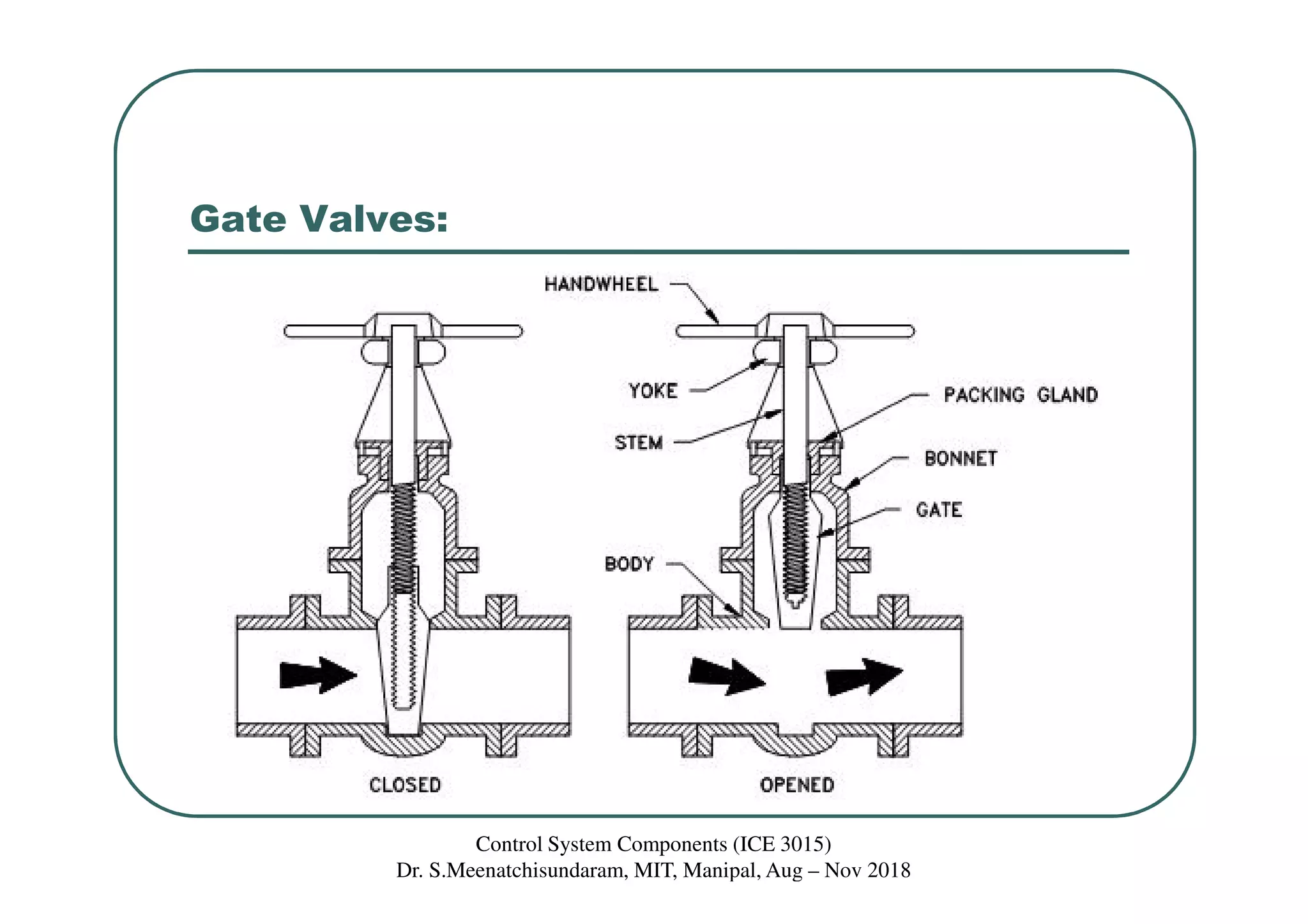
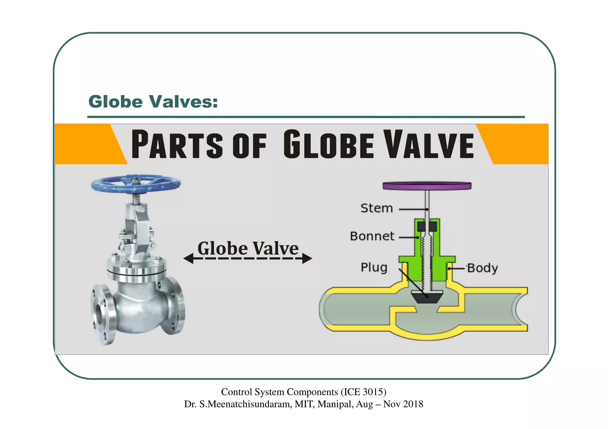
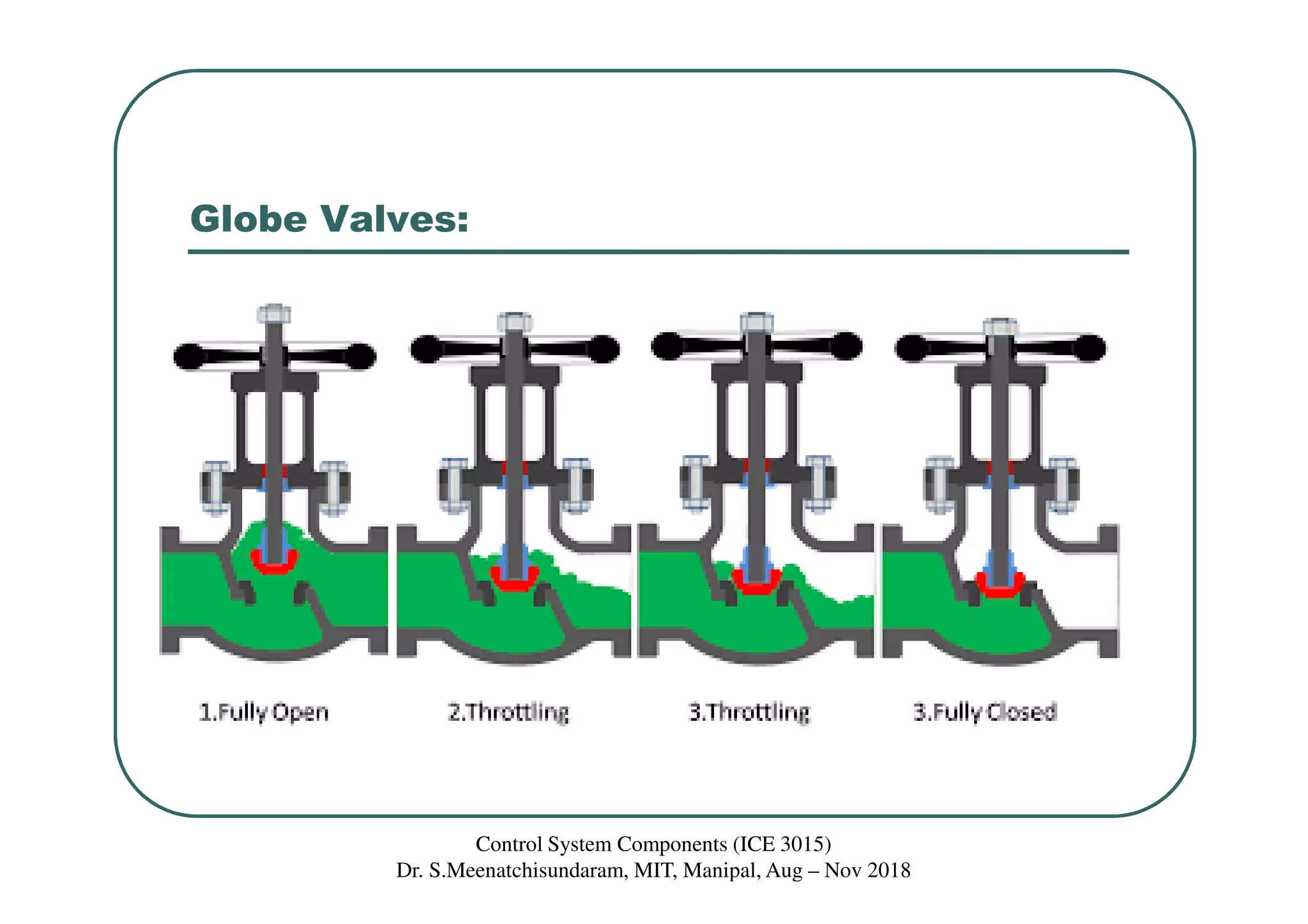
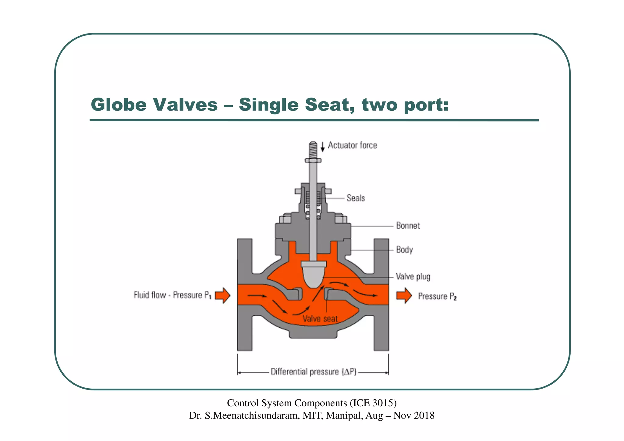
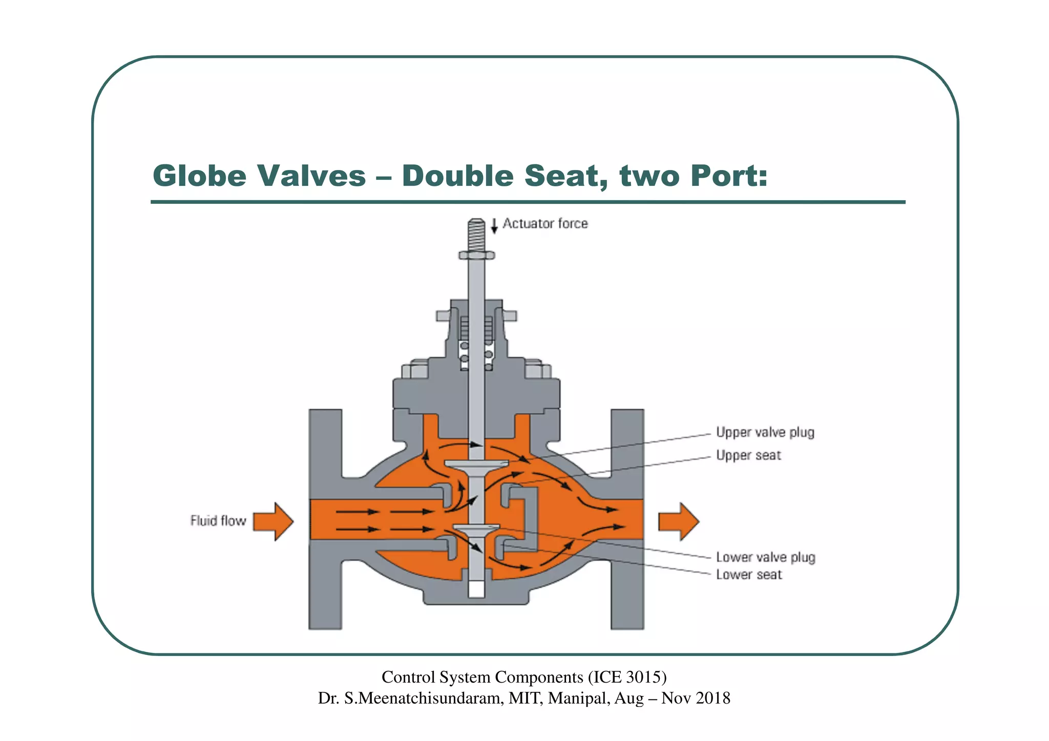
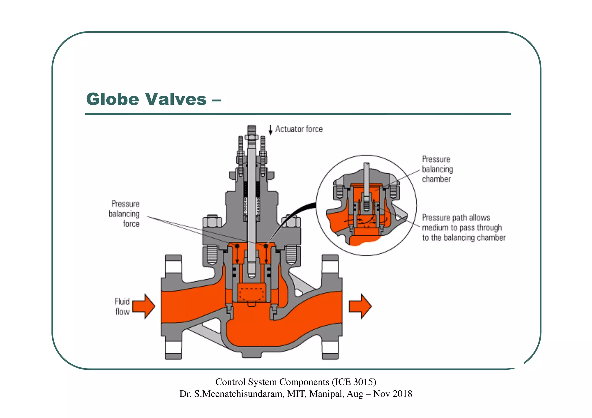
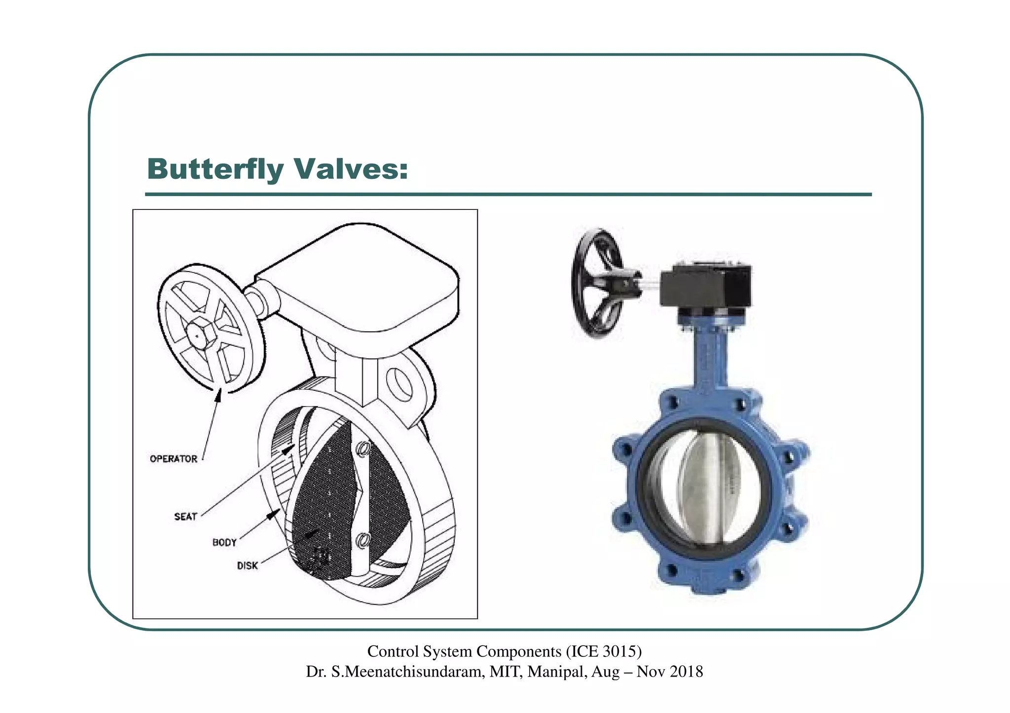
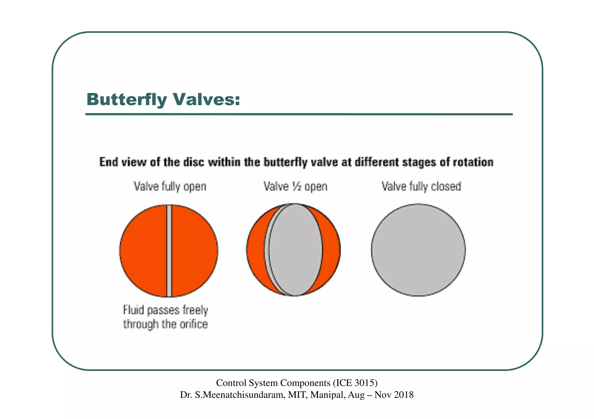
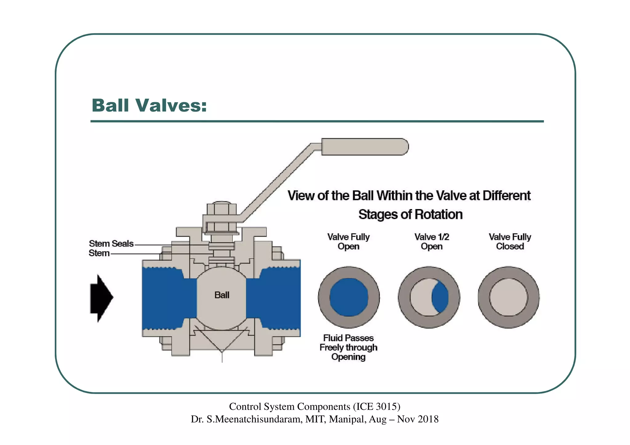
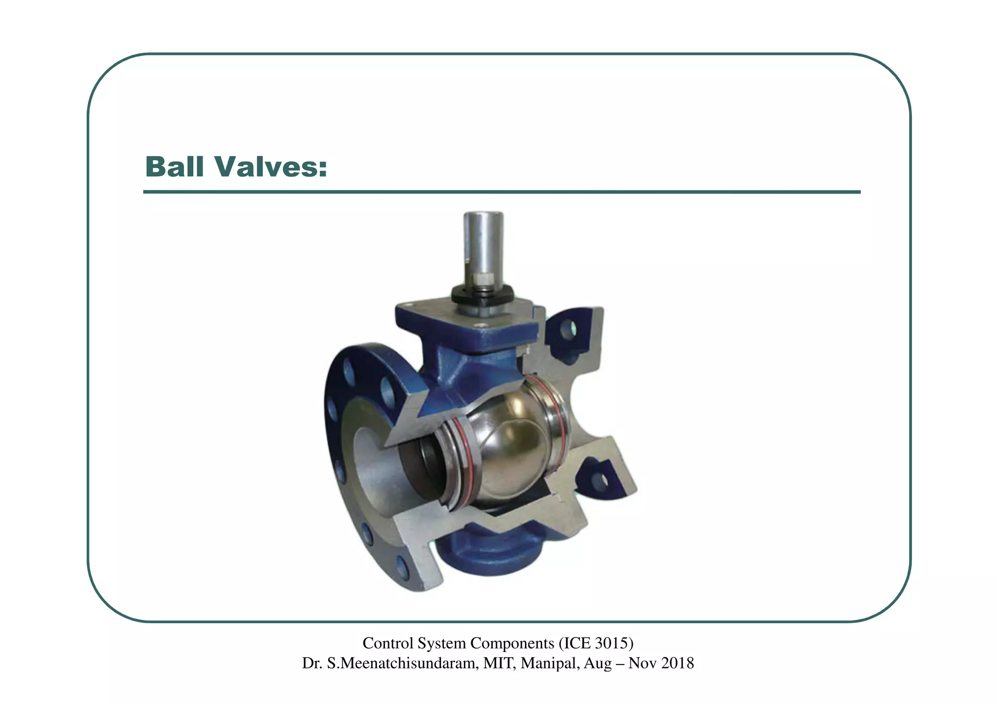
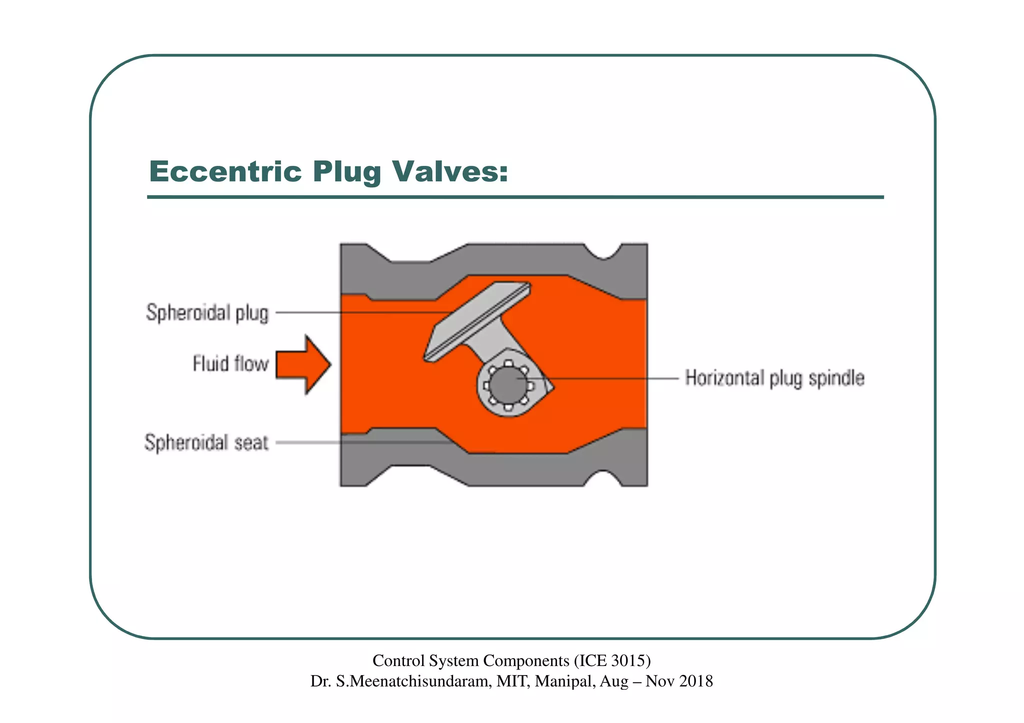
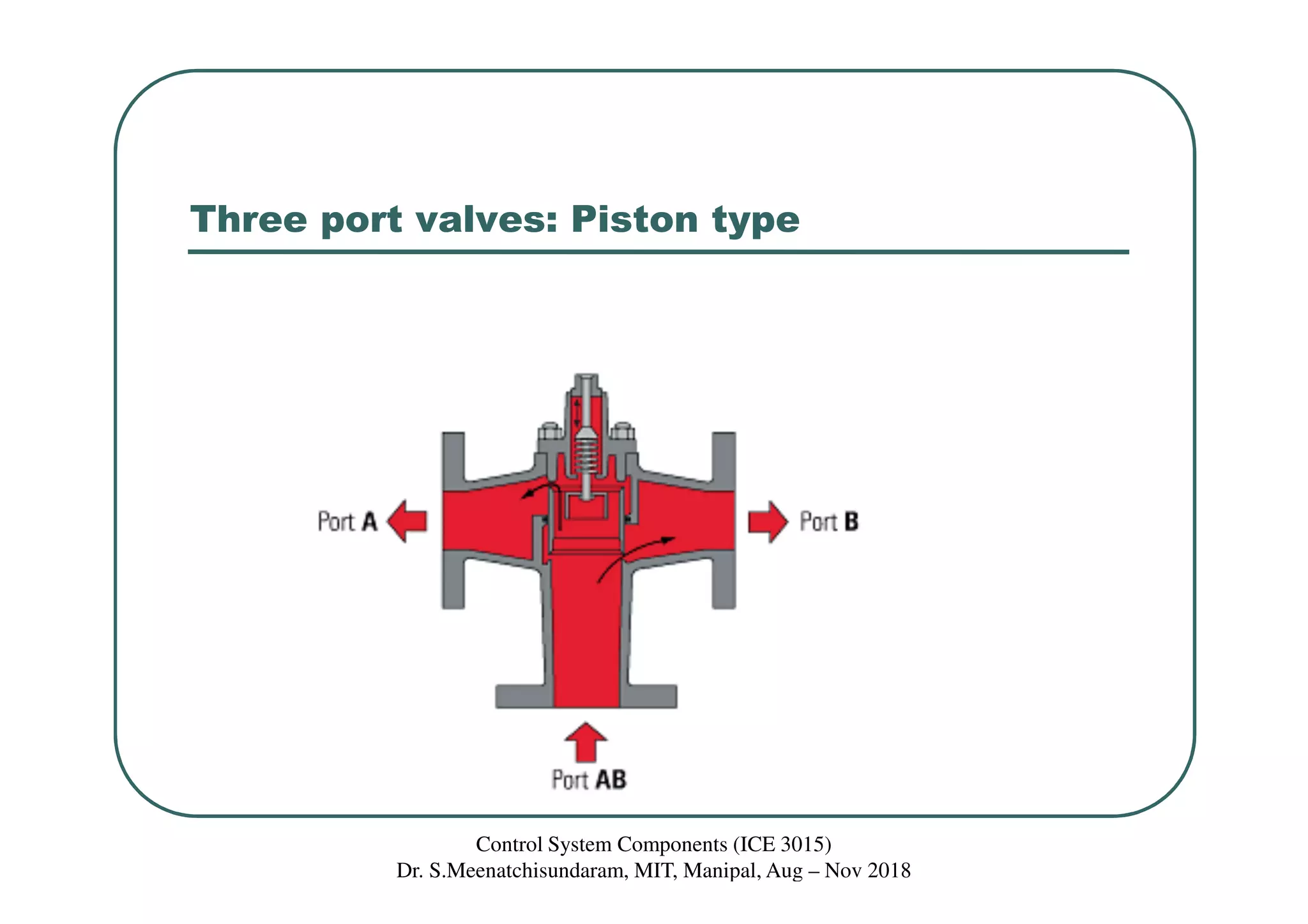
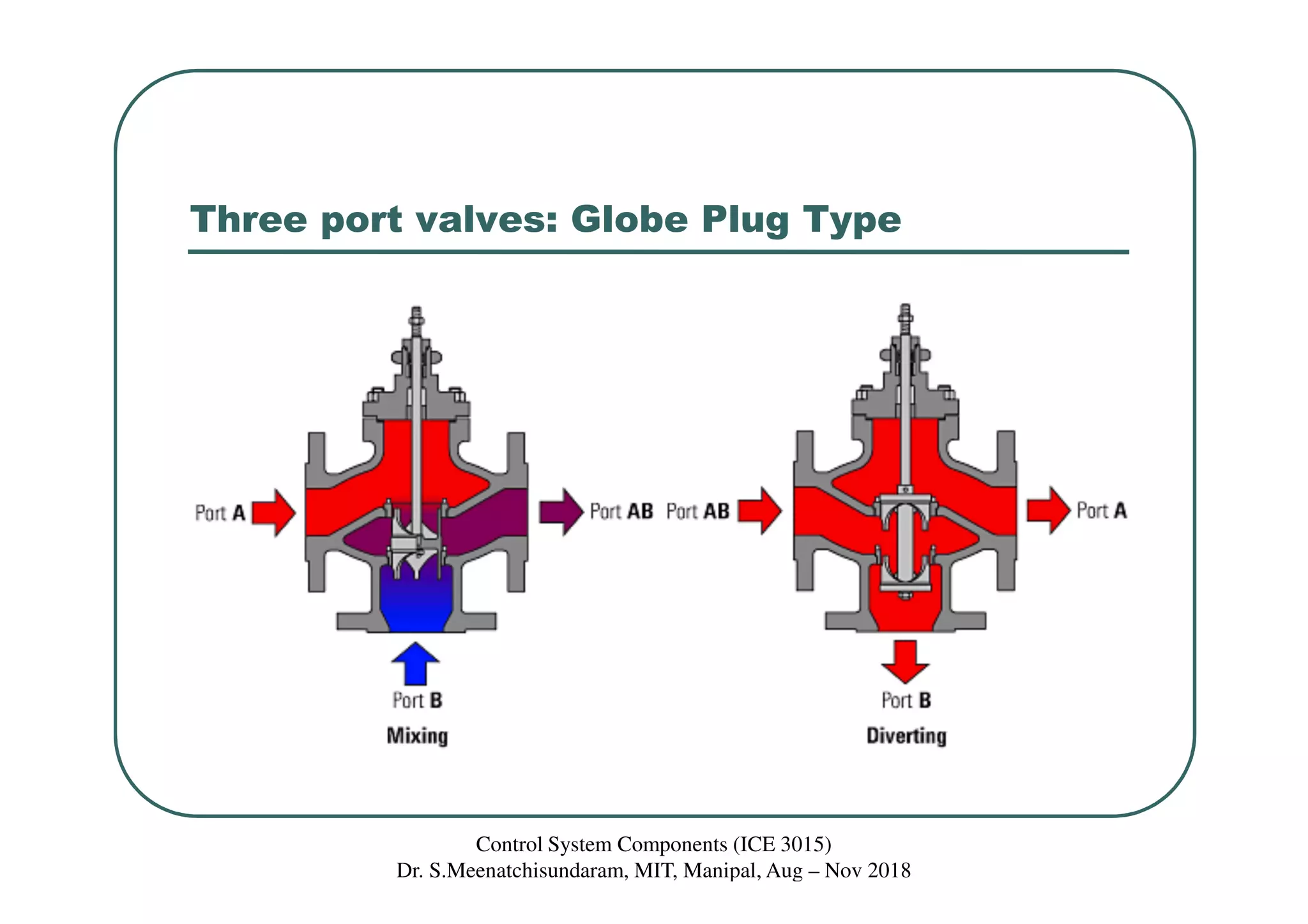
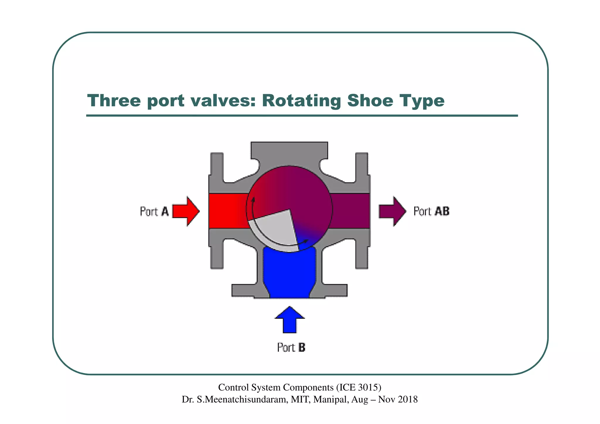
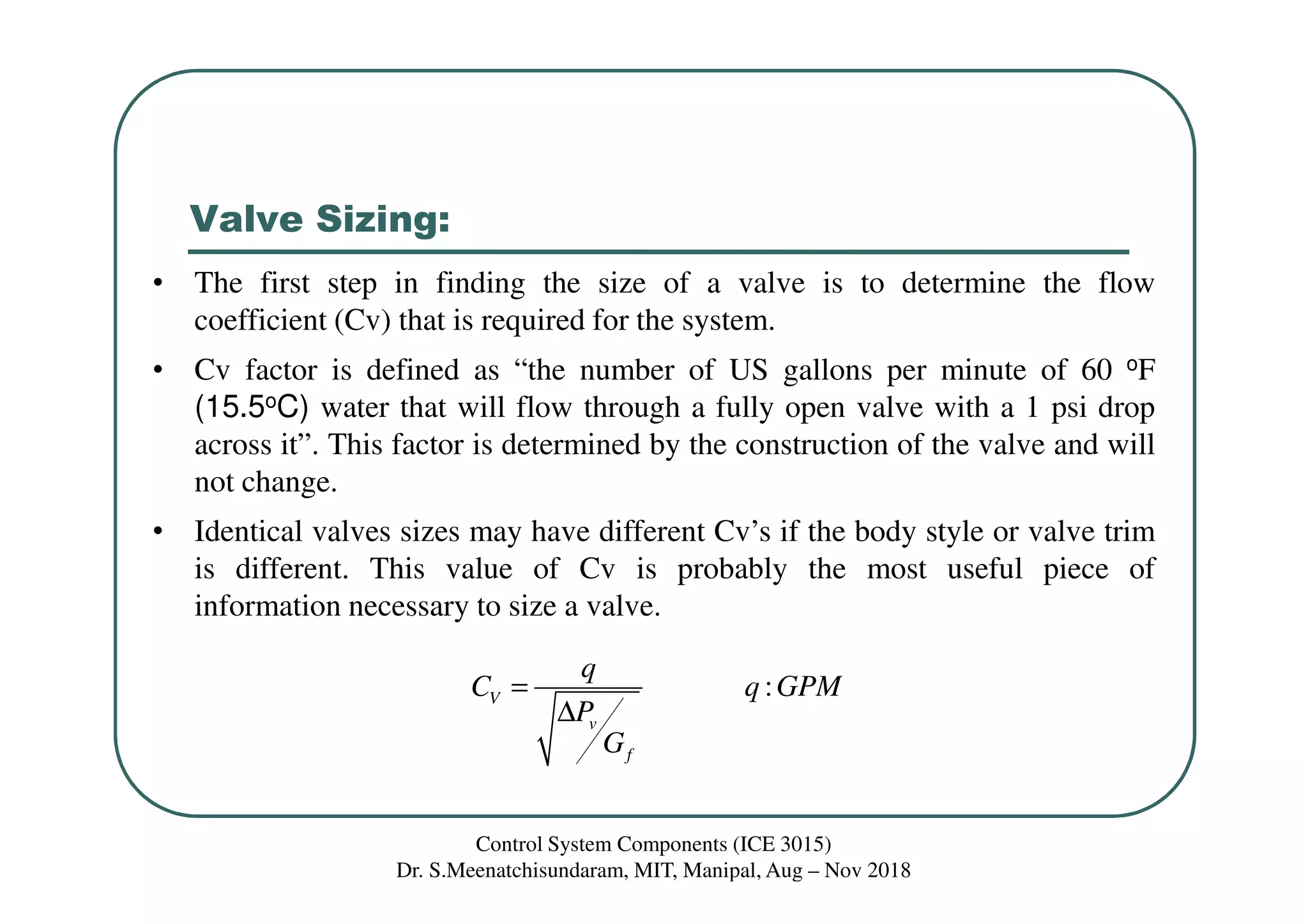
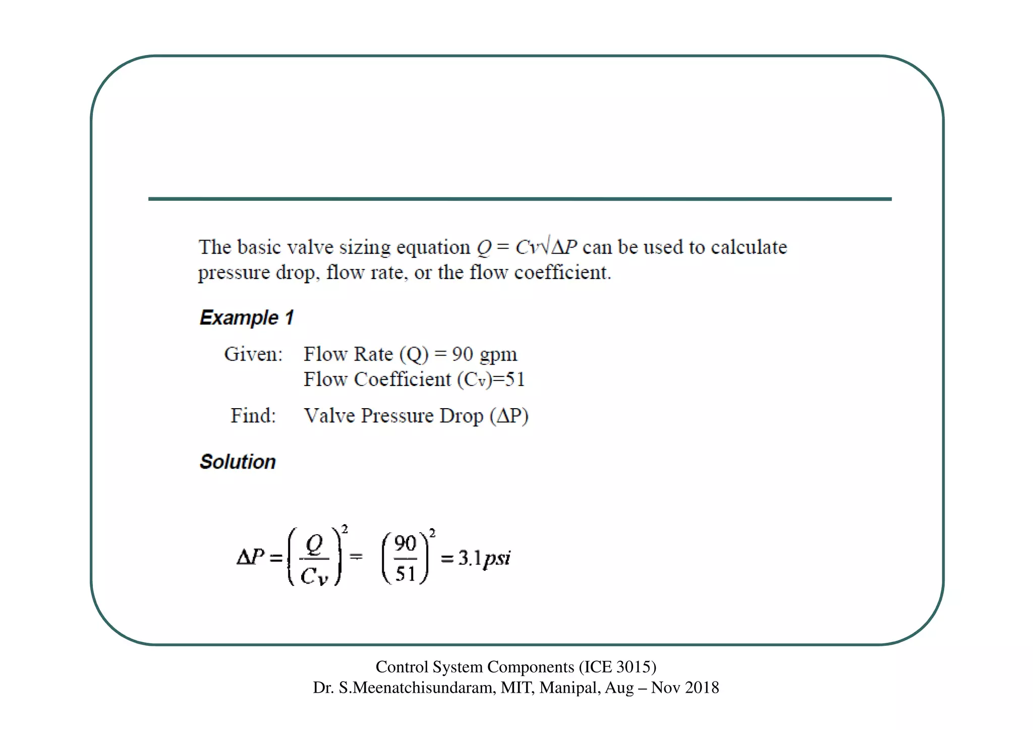
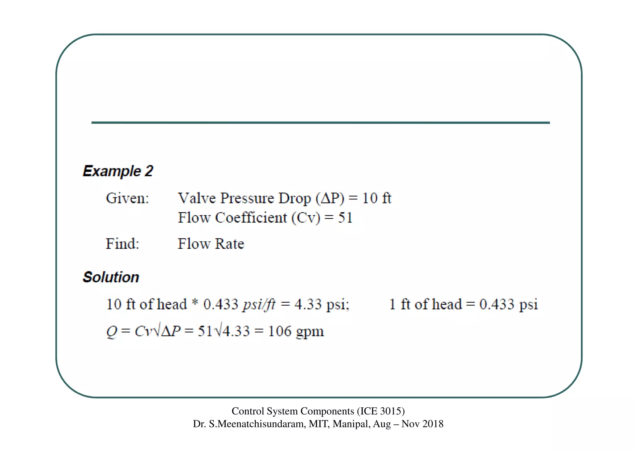
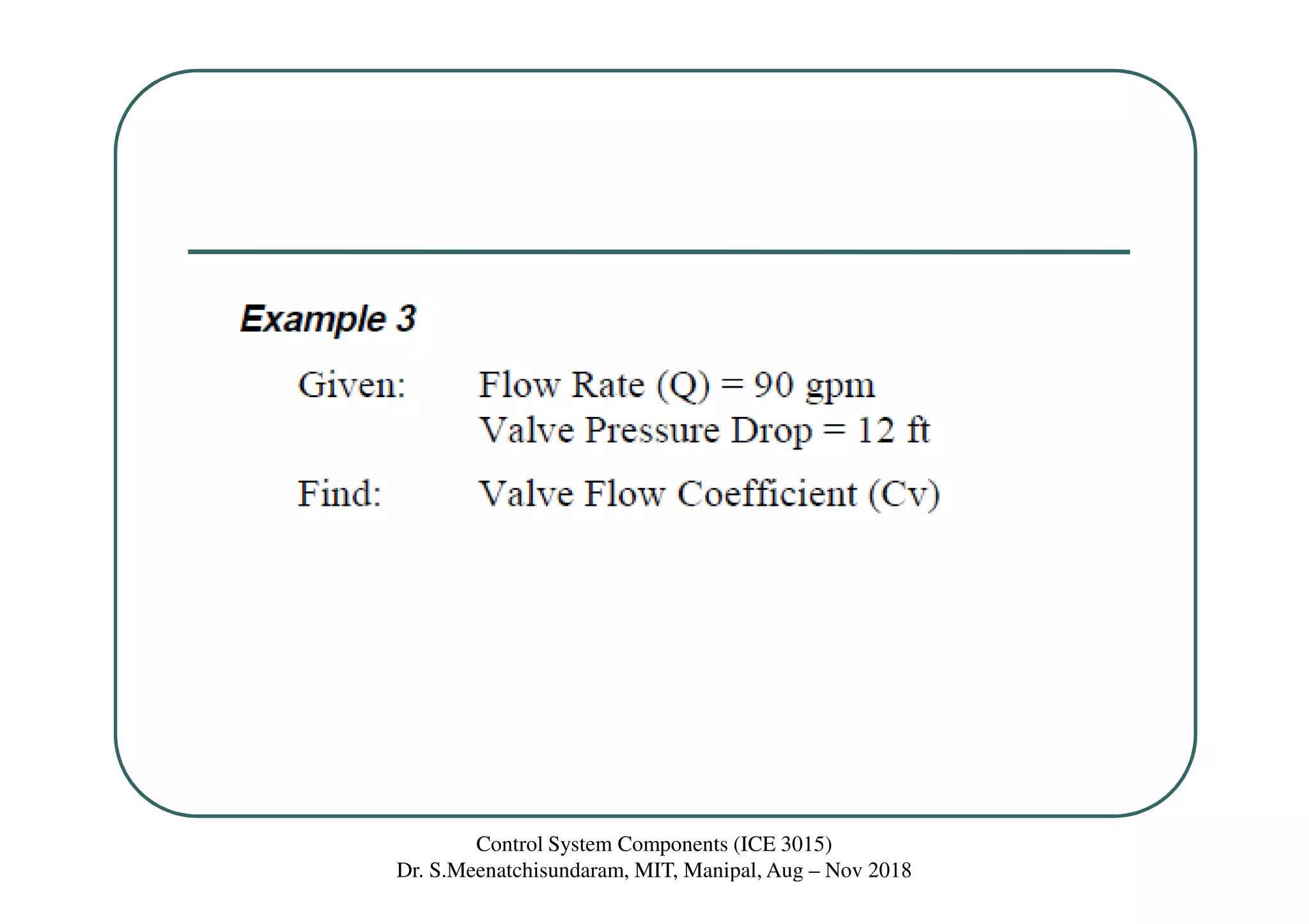
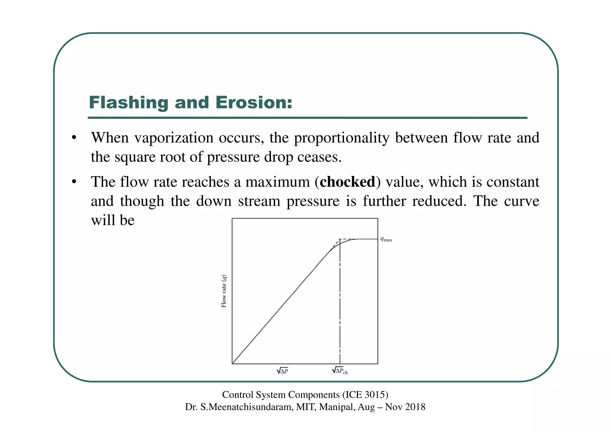
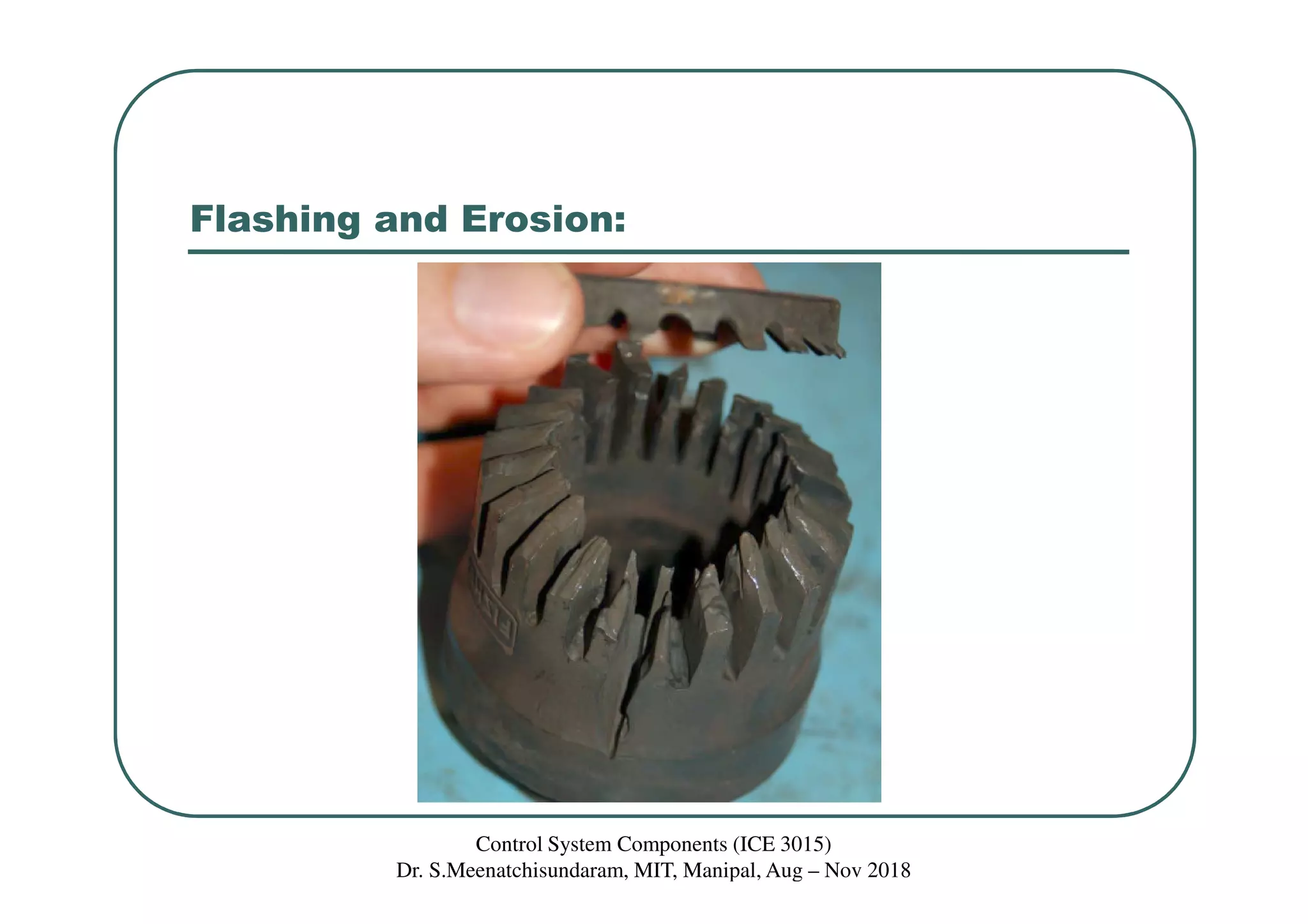
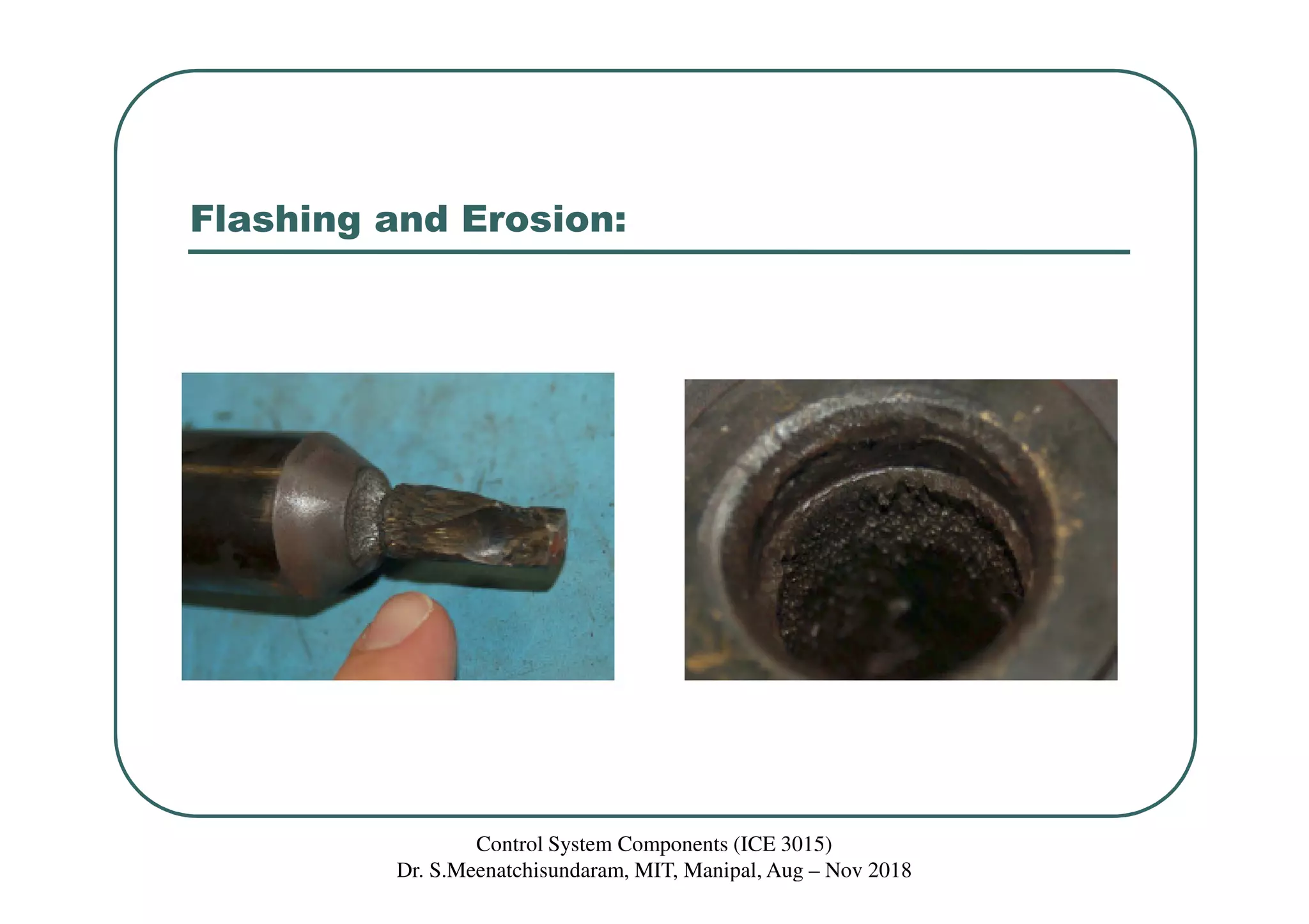

This document discusses valve types, valve positioners, cavitation, and flashing. It provides information on different types of valves like linear valves, rotary valves, angle valves, gate valves, globe valves, butterfly valves, ball valves, and eccentric plug valves. It also discusses valve positioners, cavitation, flashing, erosion, three-port valves, valve sizing, and pressure recovery factor. The document is presented as lecture material from Dr. S. Meenatchisundaram for the course ICE401: Process Instrumentation and Control.


