Download as PDF, PPTX
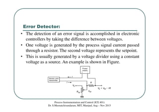
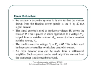
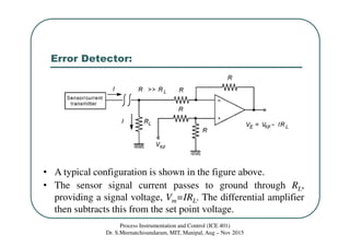
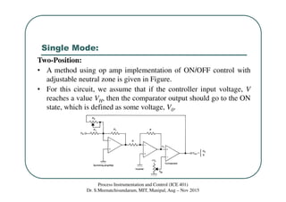
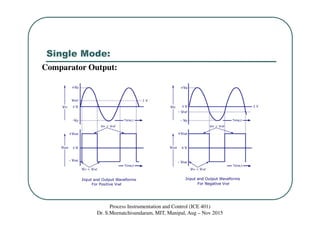
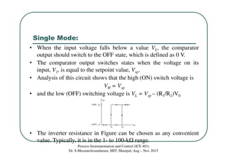

This document discusses error detectors and two-position controllers in electronic process instrumentation. It describes how an error detector takes the difference between a process signal voltage and a setpoint voltage to calculate an error signal. It also explains how a two-position controller uses an operational amplifier comparator circuit to provide ON/OFF control output based on adjustable high and low trip points for the input voltage. The document is for an instrumentation and control course taught by Dr. S. Meenatchisundaram at MIT Manipal from August to November 2015.