Download as PDF, PPTX
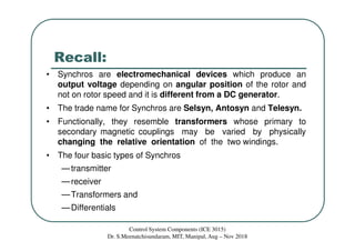
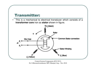
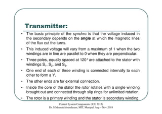
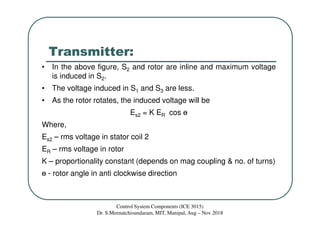
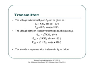
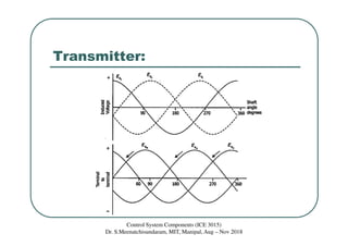
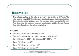
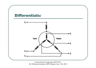

This document discusses synchros, which are electromechanical devices that produce an output voltage based on the angular position of the rotor rather than the rotor speed. There are four basic types: transmitters, receivers, transformers, and differentials. Transmitters convert mechanical rotation into electrical signals, with the voltage induced in the stator coils depending on the rotor angle. Receivers operate in reverse, using applied voltages to cause the rotor to align with the stator field. Differentials can measure the speed difference between a transmitter and receiver. The document provides examples and diagrams to illustrate the voltage relationships and functions of the different synchro components.


