Download as PDF, PPTX


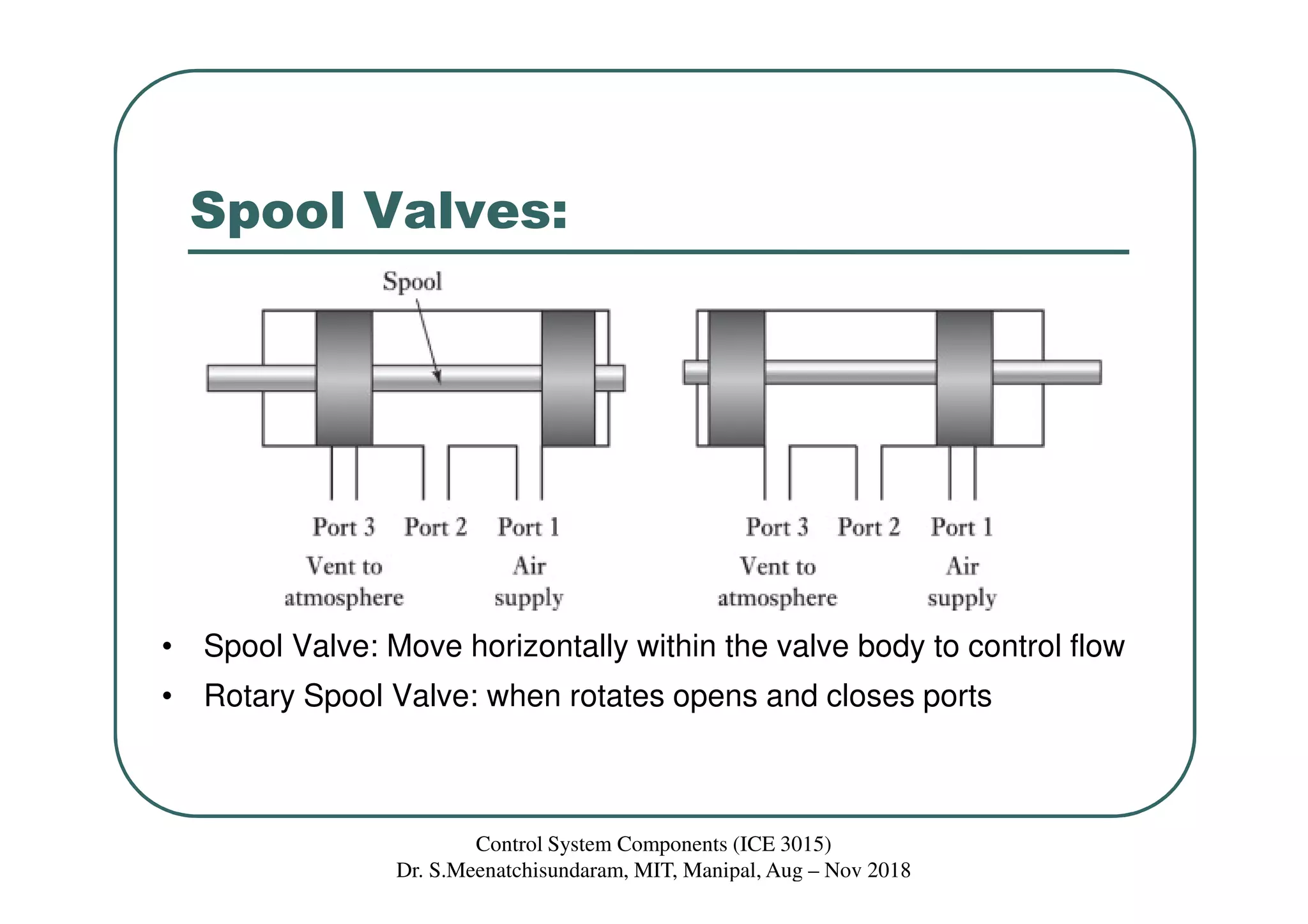

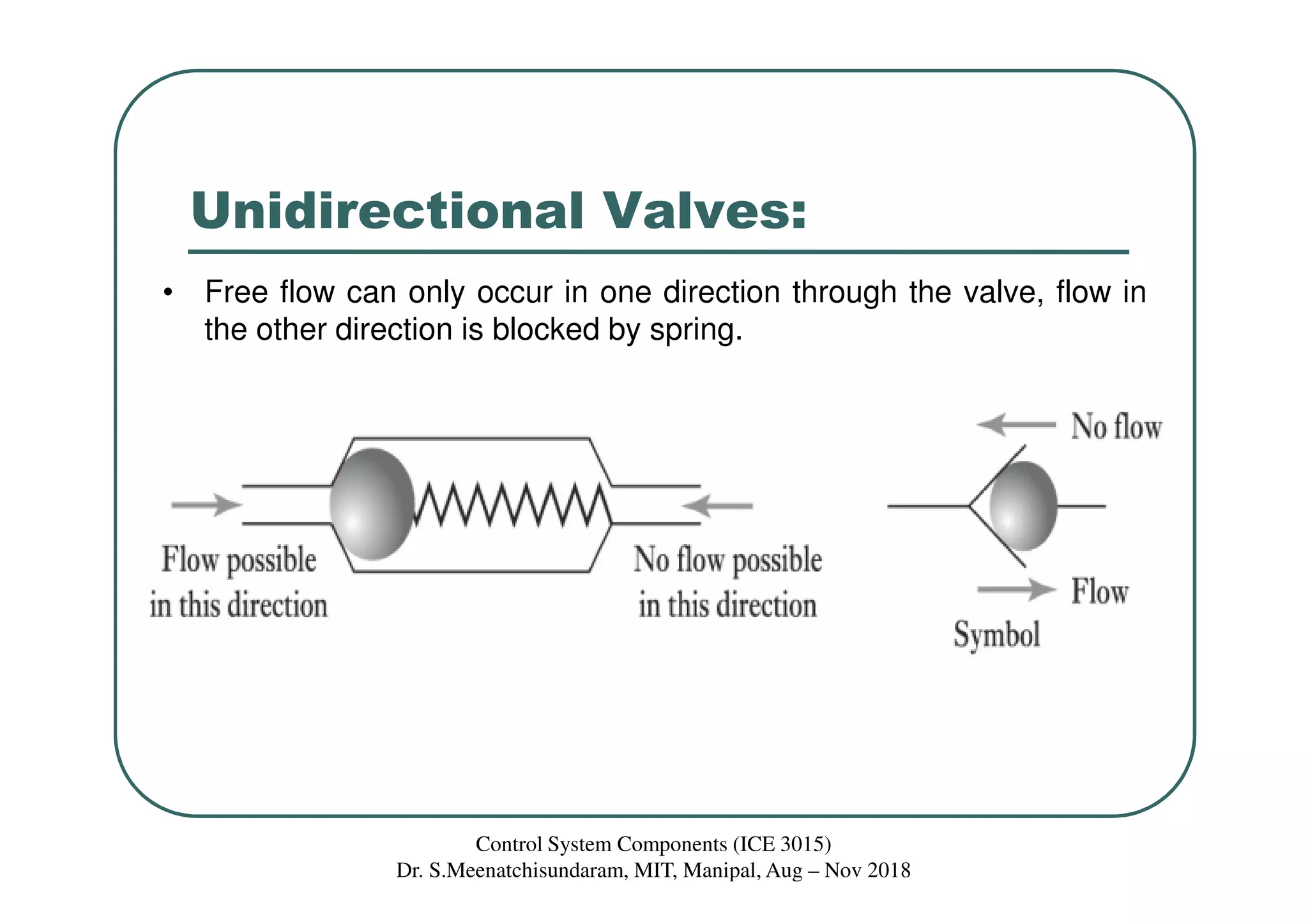


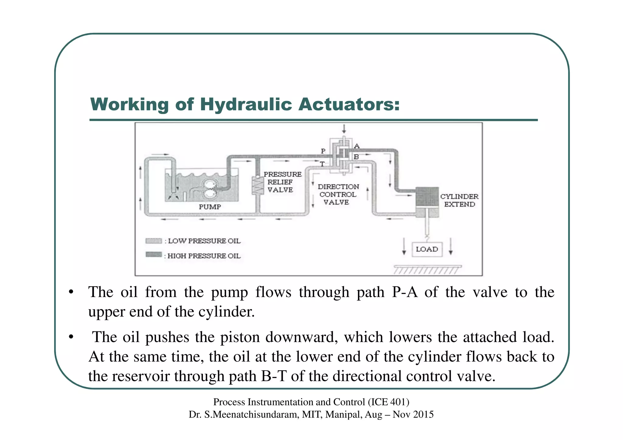

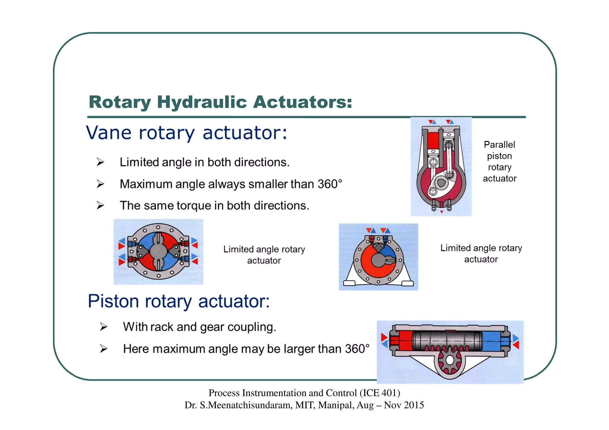


The document discusses directional control valves and their components. It describes common types of directional valves like spool valves, poppet valves, and unidirectional valves. It also discusses solenoids and pneumatic and hydraulic systems that use directional control valves to direct fluid flow. Standard symbols for different valve types are presented along with examples of their use in diagrams.


