This document outlines topics related to testing and testability for an M.Tech examination. It lists eight questions, with each question having two parts (a) and (b). The questions cover topics such as modeling digital circuits, delay models, fault models, ATPG for sequential circuits, scan architectures, boundary scan testing, DFT approaches, signature analysis, self-test design, memory testing, JTAG testing features, hazard detection, and RTS. Students must answer any five questions by explaining the related concepts in detail.
This project will provides a detailed explanation about a smart traffic light controller using verilog code along with test bench and the working principle and simulation outputs are been attached.
My new upload !!! --> http://www.slideshare.net/choleraparth91/smart-vehicle-ensuring-safe-ride-using-accerolometer-laser-sensor-co-sensor-and-also-with-use-of-gsm-modem-and-solar-panel
Contact & follow me to get PDF & PPT file - https://www.linkedin.com/in/parthcholera/
Email me directly if you want these file !!
choleraparth91@yahoo.com
or
contact me on fb - https://www.facebook.com/choleraparth91
or
https://www.facebook.com/Textivity
or
message me on - 08097508067
I suggest to go for these project !!! :D :D
synchronous Sequential circuit counters and registersDr Naim R Kidwai
The presentation covers, synchronous sequential circuits; registers and counters. design of registers, shift registers are explained. Design of counter, synchronous and ripple counter is demostrated.
Design of Elevator Controller using Verilog HDLVishesh Thakur
The aim of the project is to design and implement an Elevator/Lift Controller using Verilog hardware descriptive language (HDL). The Elevator Controller is a device used to control a lift motion and to indicate the direction of motion, and the present floor level, etc. The device controls the lift motion by means of accepting the floor level as input and generate control signals (for control the lift motion) as output. The elevator controller is based on the concept of finite state machine technology. According to the FSM technology the elevator process can be defined with the help of different states. In the FSM technology there is a change from one state to another state likewise in the elevator there will be a change from one floor to another. Every possible way is assigned a path and the implemented based on FSM concept to write the program code for elevator controller. The whole program is designed in such a way that there are desirable switches in each floor and also inside the elevator to control the user commands. While the elevator is in the ground level in order to go upward direction we need only the up switch and nothing else. The same procedure we follow for the top floor. There is only one down switch there to move downward. But in between the ground floor and top floor all other floors contain two switches, one for moving up and another for moving down. Inside the elevator there must be at least ‘n’ switches for the implementation of an ‘n’ floor elevator controller. The elevator will move according to the desirable input that is given by the user. The design includes a simple scheme that aims at a good speed of response without requiring any extra logic circuitry.
A fundamental introduction to Intellectual Property in VLSI domain. Starts from basics and includes types of IPs and their examples, life cycle of an IP and other few topics in brief in an interactive Q-A manner.
The material is also available at : https://wordpress.com/stats/day/vlsifundamentals.wordpress.com
This presentation discusses the basics about how to realize logic functions using Static CMOS logic. This presentation discusses about how to realize a Boolean expression by drawing a Pull-up network and a pull-down network. It also briefs about the pass transistor logic and the concepts of weak and strong outputs.
Sampling is fundamental process to move towards digitalization, which converts analog signal into discrete samples. Sampling theorem gives minimum sampling rate requirement so as to recover original message signal. After sampling original signal can be reconstructed without distortion, only if it is a band limited signal.
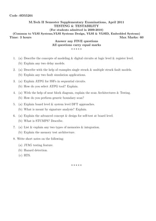
1. Code :9D55201
M.Tech II Semester Supplementary Examinations, April 2011
TESTING & TESTABILITY
(For students admitted in 2009-2010)
(Common to VLSI Systems,VLSI Systems Design, VLSI & VLSID, Embedded Systems)
Time: 3 hours Max Marks: 60
Answer any FIVE questions
All questions carry equal marks
⋆ ⋆ ⋆ ⋆ ⋆
1. (a) Describe the concepts of modeling & digital circuits at logic level & register level.
(b) Explain any two delay models.
2. (a) Describe with the help of examples single struck & multiple struck fault models.
(b) Explain any two fault simulation applications.
3. (a) Explain ATPG for SSFs in sequential circuits.
(b) How do you select ATPG tool? Explain.
4. (a) With the help of neat block diagram, explain the scan Architectures & Testing.
(b) How do you perform generic boundary scan?
5. (a) Explain board level & system level DFT approaches.
(b) What is meant by signature analysis? Explain.
6. (a) Explain the advanced concept & design for self-test at board level.
(b) What is STUMPS? Describe.
7. (a) List & explain any two types of memories & integration.
(b) Explain the memory test architecture.
8. Write short notes on the following:
(a) JTAG testing feature.
(b) Hazard detection.
(c) RTS.
⋆ ⋆ ⋆ ⋆ ⋆