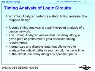
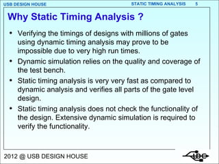
TIMING ANALYSIS OF  LOGIC CIRCUITS
Post layout simulation HDL Implementation Design Cycle DESIGN ENTRY Schematic , VHDL, Verilog, etc. Functional Simulation SYNTHESIS Test insertion Gate level simulation Implementation MAP, PLACE , ROUTE Static Timing Analysis Static Timing Analysis Libraries Constraints
The Timing Analyzer performs a static timing analysis of a mapped design A static timing analysis is a point-to-point analysis of a design network. The Timing Analyzer verifies that the delay along a given path or paths meets your specified timing requirements. It organizes and displays data that allows you to analyze the critical paths in your circuit, the cycle time of the circuit, the delay along any specified paths. Timing Analysis of Logic Circuits
Static timing analysis is performed at various stages of the design flow viz. after synthesis, after test insertion, after layout, etc. Your design's system performance is limited by some basic types of timing paths. Each of these paths goes through a sequence of logic, routing, and logic. Timing Analysis of Logic Circuits
Why Static Timing Analysis ? Verifying the timings of designs with millions of gates using dynamic timing analysis may prove to be impossible due to very high run times.  Dynamic simulation relies on the quality and coverage of the test bench.  Static timing analysis is very very fast as compared to dynamic analysis and verifies all parts of the gate level design. Static timing analysis does not check the functionality of the design. Extensive dynamic simulation is required to verify the functionality.
Pad to Pad A pad-to-pad path starts at an input pad of the chip, propagates through one or more levels of combinational logic, and ends at an output pad of the chip. The pad-to-pad path time is the maximum time required for the data to enter the chip, travel through logic & routing, and leave the chip.  It is not controlled or affected by any clock signal.
Pad To Pad
Pad to Setup  A pad-to-setup path starts at an input pad of the chip, propagates through input buffers and any number of combinatorial logic levels, and end at a D/T input to a flip-flop, latch or the receiving flip-flop’s t setup. Pad-to-set paths do not travel through flip-flops. The pad-to-setup path time is the maximum time required for the data to enter the chip, travel through logic and routing, and arrive at the input (D/T) before the clock or control signal arrives.
Pad To Setup
Clock To Pad Paths  A clock-to-pad path starts at a clock input of a flip-flop, propagates through the flip-flop Q output and any number of levels of  combinatorial logic, and ends at an output pad.  It includes the clock-to-Q delay (Tpff) of the flip-flop and the path delay from that flip-flop to the chip output. The clock-to-pad path time is the maximum time required for the data to leave the source flip-flop, travel through logic & routing, and leave the chip.
Clock To Pad Paths
Clock To Pad Through Tristates
These are not valid clock to pad paths.
Clock To Setup - Same Clock
Rising Edge To Falling Edge Timing
Falling Edge To Rising Edge
Clock To Setup - Different Clocks
The paths ending at the clock pin of other FFs or the asynchronous pins of other FFs are not valid clock to setup paths. Clock enable pins ? They are similar to data. They will also have setup requirement.
Clock Pad To Clock Pin Of F/Fs
E.g. 1 What is the minimum clock period (Tmin) for this circuit? Hint: Evaluate all FF to FF paths
E.g. 1 contd. Path FFA to FFB TClk-Q(FFA) + Tpd(H) + Ts(FFB) =  5ns + 5ns+ 2ns = 12ns Path FFB to FFB TCLK-Q(FFB) + Tpd(F) + Tpd(H) + Ts(FFB) =  4ns + 4ns + 5ns + 2n = 15 ns   So, Tmin=15 ns.
E.g. 2 Analysis of All The Paths In The Circuit
E.g. 2 Analysis of All The Paths In The Circuit Data at A, B, C and D is stable for 3 ns after the rising clock edge Data at X and Y has to be stable 3 ns before the rising clock edge. Calculate the maximum frequency of operation of the circuit. The delays are  Tpd AND,OR= 1 ns, Tpd XOR= 2 ns, Tsetup= 1 ns, TclocktoQ  = 3 ns.
E.g. 2 contd. Pad to Pad A to Y: (i) Tin-G4-Tout = 3+1+3=7ns (ii) Tin-G1-G4-Tout = 3+1+1+3=8ns
Pad to clock A-FF2D (i) Tin-G4-G7-TsetupFF2 =3+1+2+1=7ns (ii) Tin-G1-G4-G7-TsetupFF2 =3+1+1+2+1=8ns (iii) Tin-G5-G6-G7-TsetupFF2    =3+1+1+1+2+1=9ns C-FF2D: Tin-G3-G7-TsetupFF2 =3+1+2+1=7ns D-FF2D: Tin-G2-G5-G6-G7-TsetupFF2    =3+1+1+1+2+1=9ns C-FF2E Tin-G8-TsetupFF2 = 3+1+1=5ns D-FF2E Tin-G2-G5-G6-G8-TsetupFF2 =3+1+1+1+1+1=8ns
Clock to clock path FF1D – FF2D:  (i)Tclk-QFF1-G1-G4-G7-TsetupFF2 = 3+1+1+2+1 = 8ns (ii) Tclk-QFF1-G1-G5-G6-G7-TsetupFF2 = 3+1+1+1+2+1 = 9ns (iii) Tclk-QFF1-G2-G5-G6-G7-TsetupFF2 = 3+1+1+1+2+1 = 9ns (iv)Tclk-QnFF1-G6-G7-TsetupFF2 = 3+1+2+1 = 7ns (iv)Tclk-QnFF1-G3-G7-TsetupFF2 = 3+1+2+1 = 7ns
Clock to clock path (contd.) FF1D – FF2E:  (i) Tclk-QFF1-G1-G5-G6-G8-TsetupFF2 = 3+1+1+1+1+1 = 8ns (ii) Tclk-QFF1-G2-G5-G6-G8-TsetupFF2 = 3+1+1+1+1+1 = 8ns (iii)Tclk-QnFF1-G6-G8-TsetupFF2 = 3+1+1+1 = 6ns
Clock to Pad  FF1 – Y:  (i) Tclk-QFF1-G1-G4-Tout = 3+1+1+3 = 8ns FF2 – X (i) Tclk-QFF2-Tout = 3+3 = 6ns Maximum period between clk to clk paths is 9 ns Maximum frequency of operation = 1/9  =111.11 Mhz
THANK YOU

Timing Analysis

  • 1.
    TIMING ANALYSIS OF LOGIC CIRCUITS
  • 2.
    Post layout simulationHDL Implementation Design Cycle DESIGN ENTRY Schematic , VHDL, Verilog, etc. Functional Simulation SYNTHESIS Test insertion Gate level simulation Implementation MAP, PLACE , ROUTE Static Timing Analysis Static Timing Analysis Libraries Constraints
  • 3.
    The Timing Analyzerperforms a static timing analysis of a mapped design A static timing analysis is a point-to-point analysis of a design network. The Timing Analyzer verifies that the delay along a given path or paths meets your specified timing requirements. It organizes and displays data that allows you to analyze the critical paths in your circuit, the cycle time of the circuit, the delay along any specified paths. Timing Analysis of Logic Circuits
  • 4.
    Static timing analysisis performed at various stages of the design flow viz. after synthesis, after test insertion, after layout, etc. Your design's system performance is limited by some basic types of timing paths. Each of these paths goes through a sequence of logic, routing, and logic. Timing Analysis of Logic Circuits
  • 5.
    Why Static TimingAnalysis ? Verifying the timings of designs with millions of gates using dynamic timing analysis may prove to be impossible due to very high run times. Dynamic simulation relies on the quality and coverage of the test bench. Static timing analysis is very very fast as compared to dynamic analysis and verifies all parts of the gate level design. Static timing analysis does not check the functionality of the design. Extensive dynamic simulation is required to verify the functionality.
  • 6.
    Pad to PadA pad-to-pad path starts at an input pad of the chip, propagates through one or more levels of combinational logic, and ends at an output pad of the chip. The pad-to-pad path time is the maximum time required for the data to enter the chip, travel through logic & routing, and leave the chip. It is not controlled or affected by any clock signal.
  • 7.
  • 8.
    Pad to Setup A pad-to-setup path starts at an input pad of the chip, propagates through input buffers and any number of combinatorial logic levels, and end at a D/T input to a flip-flop, latch or the receiving flip-flop’s t setup. Pad-to-set paths do not travel through flip-flops. The pad-to-setup path time is the maximum time required for the data to enter the chip, travel through logic and routing, and arrive at the input (D/T) before the clock or control signal arrives.
  • 9.
  • 10.
    Clock To PadPaths A clock-to-pad path starts at a clock input of a flip-flop, propagates through the flip-flop Q output and any number of levels of combinatorial logic, and ends at an output pad. It includes the clock-to-Q delay (Tpff) of the flip-flop and the path delay from that flip-flop to the chip output. The clock-to-pad path time is the maximum time required for the data to leave the source flip-flop, travel through logic & routing, and leave the chip.
  • 11.
  • 12.
    Clock To PadThrough Tristates
  • 13.
    These are notvalid clock to pad paths.
  • 14.
    Clock To Setup- Same Clock
  • 15.
    Rising Edge ToFalling Edge Timing
  • 16.
    Falling Edge ToRising Edge
  • 17.
    Clock To Setup- Different Clocks
  • 18.
    The paths endingat the clock pin of other FFs or the asynchronous pins of other FFs are not valid clock to setup paths. Clock enable pins ? They are similar to data. They will also have setup requirement.
  • 19.
    Clock Pad ToClock Pin Of F/Fs
  • 20.
    E.g. 1 Whatis the minimum clock period (Tmin) for this circuit? Hint: Evaluate all FF to FF paths
  • 21.
    E.g. 1 contd.Path FFA to FFB TClk-Q(FFA) + Tpd(H) + Ts(FFB) = 5ns + 5ns+ 2ns = 12ns Path FFB to FFB TCLK-Q(FFB) + Tpd(F) + Tpd(H) + Ts(FFB) = 4ns + 4ns + 5ns + 2n = 15 ns So, Tmin=15 ns.
  • 22.
    E.g. 2 Analysisof All The Paths In The Circuit
  • 23.
    E.g. 2 Analysisof All The Paths In The Circuit Data at A, B, C and D is stable for 3 ns after the rising clock edge Data at X and Y has to be stable 3 ns before the rising clock edge. Calculate the maximum frequency of operation of the circuit. The delays are Tpd AND,OR= 1 ns, Tpd XOR= 2 ns, Tsetup= 1 ns, TclocktoQ = 3 ns.
  • 24.
    E.g. 2 contd.Pad to Pad A to Y: (i) Tin-G4-Tout = 3+1+3=7ns (ii) Tin-G1-G4-Tout = 3+1+1+3=8ns
  • 25.
    Pad to clockA-FF2D (i) Tin-G4-G7-TsetupFF2 =3+1+2+1=7ns (ii) Tin-G1-G4-G7-TsetupFF2 =3+1+1+2+1=8ns (iii) Tin-G5-G6-G7-TsetupFF2 =3+1+1+1+2+1=9ns C-FF2D: Tin-G3-G7-TsetupFF2 =3+1+2+1=7ns D-FF2D: Tin-G2-G5-G6-G7-TsetupFF2 =3+1+1+1+2+1=9ns C-FF2E Tin-G8-TsetupFF2 = 3+1+1=5ns D-FF2E Tin-G2-G5-G6-G8-TsetupFF2 =3+1+1+1+1+1=8ns
  • 26.
    Clock to clockpath FF1D – FF2D: (i)Tclk-QFF1-G1-G4-G7-TsetupFF2 = 3+1+1+2+1 = 8ns (ii) Tclk-QFF1-G1-G5-G6-G7-TsetupFF2 = 3+1+1+1+2+1 = 9ns (iii) Tclk-QFF1-G2-G5-G6-G7-TsetupFF2 = 3+1+1+1+2+1 = 9ns (iv)Tclk-QnFF1-G6-G7-TsetupFF2 = 3+1+2+1 = 7ns (iv)Tclk-QnFF1-G3-G7-TsetupFF2 = 3+1+2+1 = 7ns
  • 27.
    Clock to clockpath (contd.) FF1D – FF2E: (i) Tclk-QFF1-G1-G5-G6-G8-TsetupFF2 = 3+1+1+1+1+1 = 8ns (ii) Tclk-QFF1-G2-G5-G6-G8-TsetupFF2 = 3+1+1+1+1+1 = 8ns (iii)Tclk-QnFF1-G6-G8-TsetupFF2 = 3+1+1+1 = 6ns
  • 28.
    Clock to Pad FF1 – Y: (i) Tclk-QFF1-G1-G4-Tout = 3+1+1+3 = 8ns FF2 – X (i) Tclk-QFF2-Tout = 3+3 = 6ns Maximum period between clk to clk paths is 9 ns Maximum frequency of operation = 1/9 =111.11 Mhz
  • 29.