The document outlines a project on designing a smart traffic light controller using Verilog, guided by Prof. Dr. P. Samundiswari at Pondicherry University. The project aims to create a two-way traffic light system that operates using a timing mechanism and a vehicle detection system, enhancing efficiency in traffic management. It includes detailed explanations of the working principle, block diagrams, state diagrams, and advantages and disadvantages of the proposed system.


![9
input Clk
);
reg [6:1] state;
reg ST;
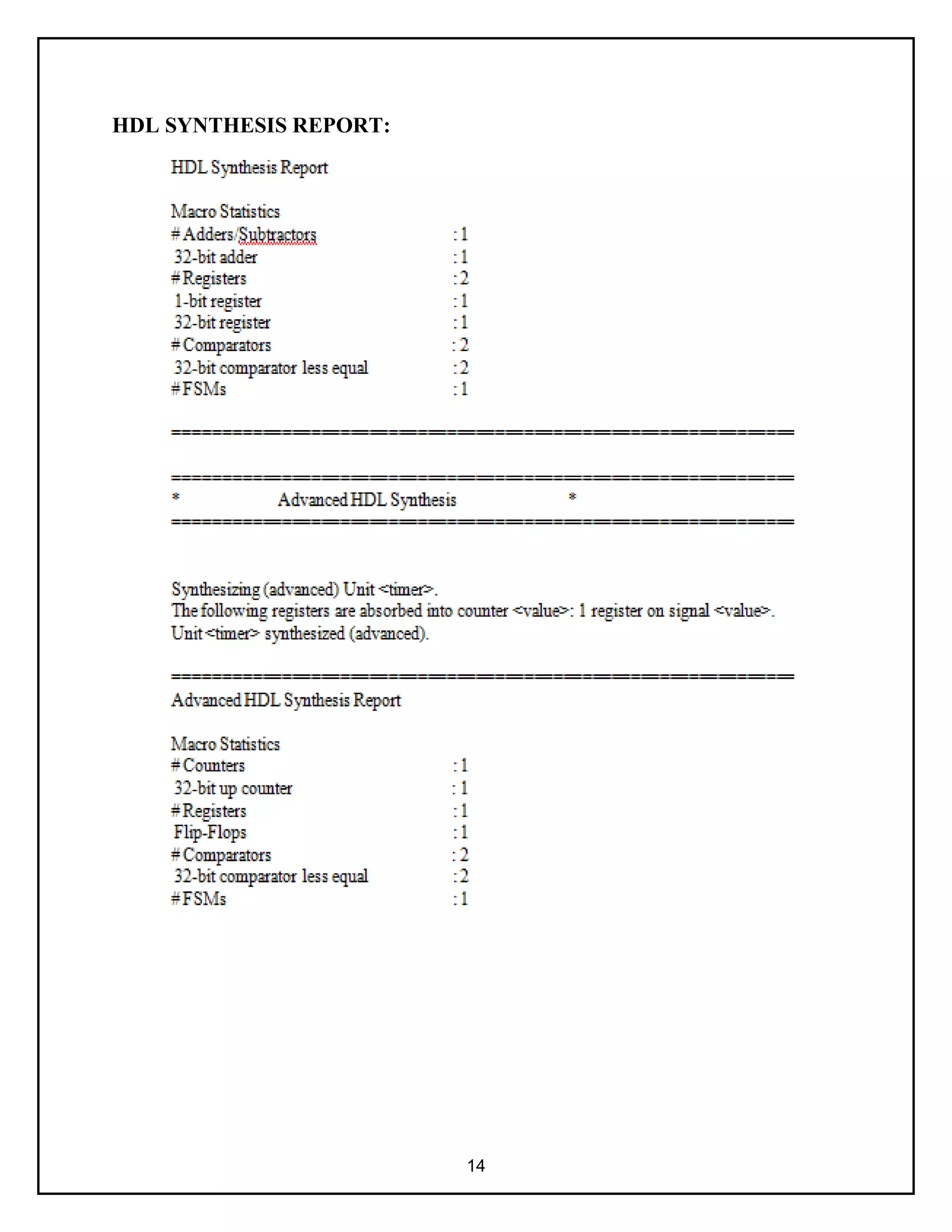
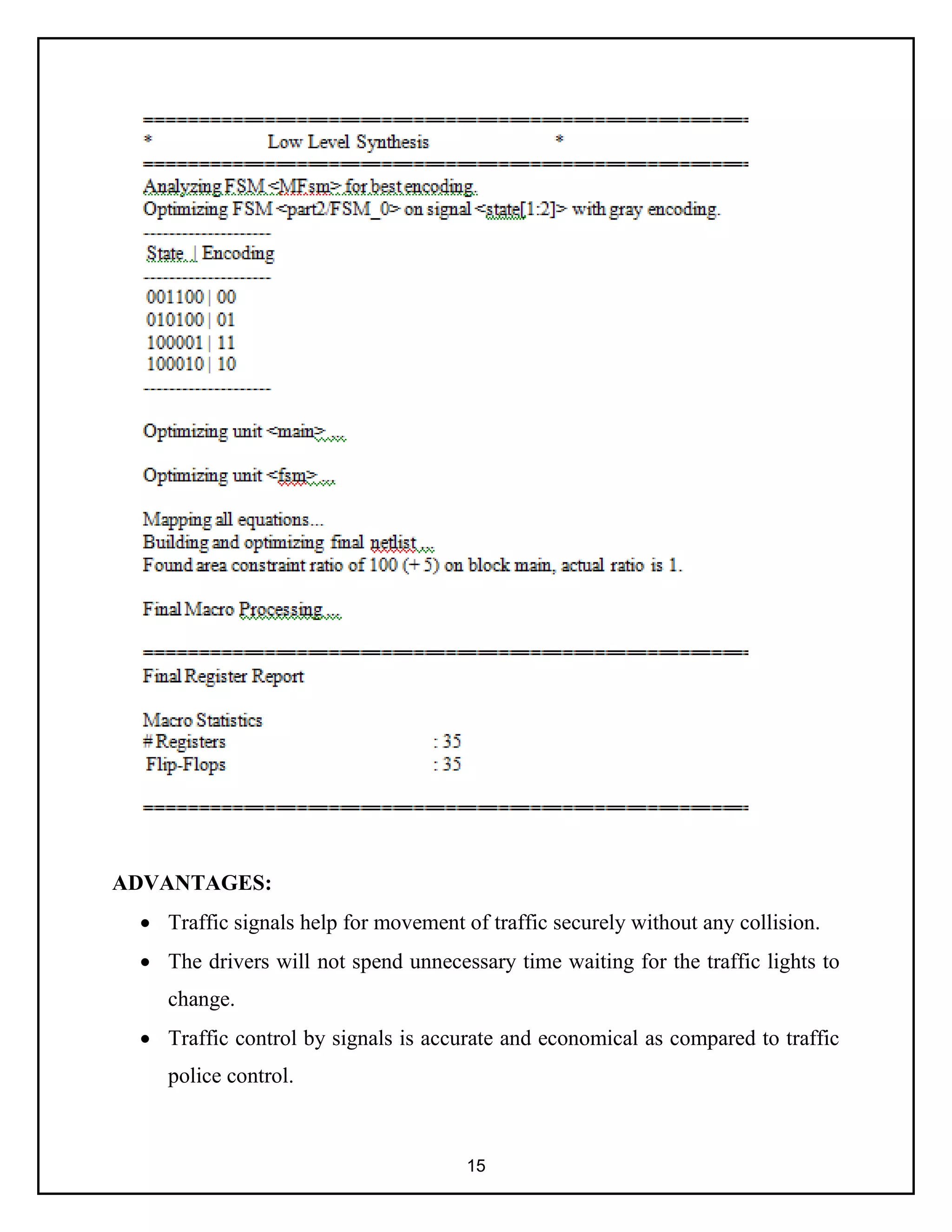
parameter mainroadgreen= 6'b001100;
parameter mainroadyellow= 6'b010100;
parameter sideroadgreen= 6'b100001;
parameter sideroadyellow= 6'b100010;
assign MR = state[6];
assign MY = state[5];
assign MG = state[4];
assign SR = state[3];
assign SY = state[2];
assign SG = state[1];
initial begin state = mainroadgreen; ST = 0; end
always @(posedge Clk)
begin
if (reset)
begin state = mainroadgreen; ST = 1; end
else
begin
ST = 0;
case (state)
mainroadgreen:
if (TL & C) begin state = mainroadyellow; ST = 1; end
mainroadyellow:](https://image.slidesharecdn.com/smarttrafficlightcontrollerbybeulahandvaishaliesandvlsiassignment-220223161733/75/Smart-traffic-light-controller-using-verilog-9-2048.jpg)


![project_ppt[1].pptx](https://cdn.slidesharecdn.com/ss_thumbnails/projectppt1-230708160322-468b41fc-thumbnail.jpg?width=640&height=640&fit=bounds)