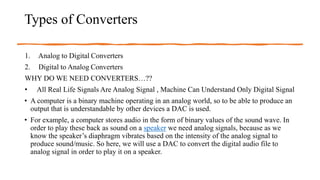
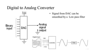
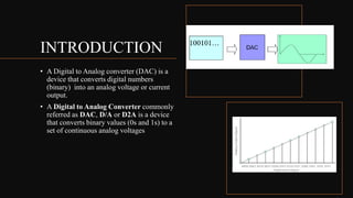
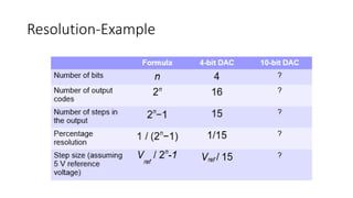
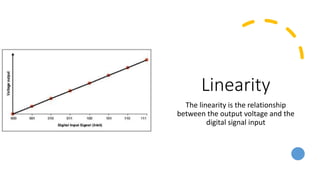
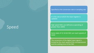
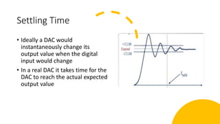
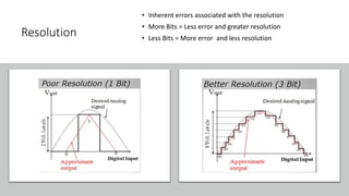
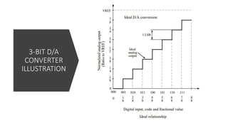
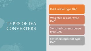
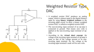
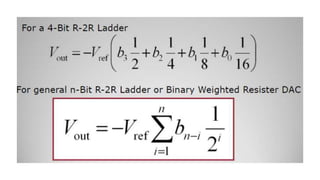
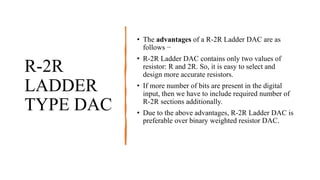
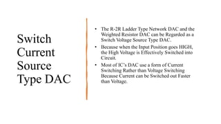
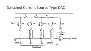
DAC FUNDAMENTALS AND
CURRENT SWITCHED&
RESISTIVE DAC
Presented by
VAIBHAVI P
INDEX
• Introduction-Analog , Discrete and Digital Signal
• Types of Converters
-A to D Converter
-D to A Converter
• Introduction-DAC
• Specifications
-Resolution
-Speed
-Linearity
-Settling Time
-Reference Voltages
-Errors
• Errors
• Types of D to A Converter
• Applications of DAC
INTRODUCTION-ANALOG,DISCRETE
AND DIGITAL SIGNAL
• Analog signal is a continuous signal in which one time-varying
quantity (such as voltage, pressure, etc.) represents another time-based
variable. In other words, one variable is an analog of the other.
• Discrete Signal-The signal which is defined for the discrete intervals
of time
• Digital Signal-The signal is discretised in both time and magnitude.
The magnitude axis is divided into fixed levels and the signal can take
value equal to these levels only
Types of Converters
1. Analog to Digital Converters
2. Digital to Analog Converters
WHY DO WE NEED CONVERTERS…??
• All Real Life Signals Are Analog Signal , Machine Can Understand Only Digital Signal
• A computer is a binary machine operating in an analog world, so to be able to produce an
output that is understandable by other devices a DAC is used.
• For example, a computer stores audio in the form of binary values of the sound wave. In
order to play these back as sound on a speaker we need analog signals, because as we
know the speaker’s diaphragm vibrates based on the intensity of the analog signal to
produce sound/music. So here, we will use a DAC to convert the digital audio file to
analog signal in order to play it on a speaker.
DATA CONVERTERS IN SIGNAL PROCESSING
Analog to Digital
Converter
Digital to Analog Converter
• Signal from DAC can be
smoothed by a Low pass filter
INTRODUCTION
• A Digital to Analog converter (DAC) is a
device that converts digital numbers
(binary) into an analog voltage or current
output.
• A Digital to Analog Converter commonly
referred as DAC, D/A or D2A is a device
that converts binary values (0s and 1s) to a
set of continuous analog voltages
Classification of DAC
Characterization and definition of Data Converters
Basic
architecture
of DAC
Converter
Static
Characterization
of D/A
Converters
Choosing a
DAC
• There are six main specifications that should
be considered when choosing a DAC for a
particular project
 Reference Voltage
Resolution
Linearity
Speed
Settling Time
Error
Resolution
• Reference voltage : To a large extent the
output properties of a DAC are determined
by the reference voltage
• Resolution is the smallest analog change
resulting from a 1 LSB digital change
(quantified in terms of N bits) Or Resolution
is the amount of variance in output
voltage for every change of the LSB in
the digital input . The voltage value is a
function of the number of input bits and
the reference voltage value
• Increasing the number of bits results in a
finite resolution
• Percentage resolution = 1 / (2n
− 1), expressed as a percentage
Step size = Vref / (2n
− 1)
Resolution-Example
Linearity
The linearity is the relationship
between the output voltage and the
digital signal input
Speed
Specified as the conversion rate or sampling rate
It is the rate at which the input register is
updated
High speed DACs are defined as operating at
greater than 1MHZ
Some state of 12-16 bit DAC can reach speeds of
1GHZ
The conversion of the digital input signal is
limited by the clock speed of the microprocessor
and the settling time of the DAC
Settling Time
• Ideally a DAC would
instantaneously change its
output value when the digital
input would change
• In a real DAC it takes time for the
DAC to reach the actual expected
output value
• Quantization Noise is the inherent uncertainty in digitizing an analog
value with a finite resolution converter.
• Full scale (FS) is the the maximum DAC analog output value. It is one LSB less
than VREF
ERROR
There are multiple
sources of error in
computing the analog
output
• Gain Error
• Offset Error
• Full scale Error
• Linearity
• Non-Monotonic Output Error
• Settling Time and Overshoot
• Resolution
Gain error
• Deviation in the slope of the
ideal curve and with respect
to the actual DAC output
• High Gain error: Step
amplitude is higher than the
desired output
• Low Gain error: Step
amplitude is lower than the
desired output
Offset Error
• Occurs when there is an
offset in the output voltage in
reference to the ideal
output.
• This error may be detected
when all input bits are low
Full scale error
• Occurs when there is an
offset in voltage form the
ideal output and a deviation
in slope from the ideal gain
Non-Linearity
• Differential nonlinearity (DNL) is the maximum deviation of any
analog output changes caused by an input LSB change from its ideal
change of or Voltage step size differences vary as digital input
increases. Ideally each step should be equivalent.
Non-Linearity
• Integral nonlinearity (INL) is
the maximum difference
between the actual finite
resolution characteristic and
the infinite resolution
characteristic. Or Occurs
when the output voltage is
non linear. Basically an
inability to adhere to the
ideal slope
Integral and
Differential Linearity
for a D/A Converter
• D/A Converter with ±1.5
LSB integral nonlinearity
and ±0.5 LSB differential
nonlinearity
Non-Monotonic
Output Error
• A monotonic D/A (A/D)
converter is one in which an
increasing digital input code
(analog input) produces a
continuously increasing
analog output value (digital
output code).
• Non-Monotonic Occurs when
the an increase in digital
input results in a lower
output voltage
Settling Time
and Overshoot
• Settling Time: The time
required for the voltage to
settle within +/- the voltage
associated with the
V(LSB).Any change in the
input time will not be
reflected immediately due to
the lag time.
• Overshoot : Occurs when the
output voltage overshoots
the desired analog output
voltage
Resolution
• Inherent errors associated with the resolution
• More Bits = Less error and greater resolution
• Less Bits = More error and less resolution
3-BIT D/A
CONVERTER
ILLUSTRATION
TYPES OF D/A
CONVERTERS
R-2R ladder type DAC
Weighted resistor type
DAC
Switched current source
type DAC
Switched capacitor type
DAC
Weighted Resistor Type
DAC
• A weighted resistor DAC produces an analog
output, which is almost equal to the digital (binary)
input by using binary weighted resistors in the
inverting adder circuit. In short, a binary weighted
resistor DAC is called as weighted resistor DAC.
• The non-inverting input terminal of an op-amp is
connected to ground. That means zero volts is
applied at the non-inverting input terminal of op-
amp.
• According to the virtual short concept, the
voltage at the inverting input terminal of op-amp is
same as that of the voltage present at its non-
inverting input terminal. So, the voltage at the
inverting input terminal’s node will be zero volts.
Weighted Resistor Type DAC
• The nodal equation at the inverting input terminal’s node is:
• Substituting, R=2Rf R=2Rf 𝑓 in above equation
.
Weighted Resistor Type DAC
• The generalized output voltage equation of an N-bit binary weighted
resistor DAC as shown below:
• The disadvantages of a binary weighted resistor DAC are as follows
−
• The difference between the resistance values corresponding to LSB &
MSB will increase as the number of bits present in the digital input
increases.
• It is difficult to design more accurate resistors as the number of bits
present in the digital input increases.
R-2R LADDER
TYPE DAC
• The R-2R Ladder DAC
overcomes the disadvantages
of a binary weighted resistor
DAC. As the name suggests,
R-2R Ladder DAC produces
an analog output, which is
almost equal to the digital
(binary) input by using a R-
2R ladder network in the
inverting adder circuit.
R-2R
LADDER
TYPE DAC
• The advantages of a R-2R Ladder DAC are as
follows −
• R-2R Ladder DAC contains only two values of
resistor: R and 2R. So, it is easy to select and
design more accurate resistors.
• If more number of bits are present in the digital
input, then we have to include required number of
R-2R sections additionally.
• Due to the above advantages, R-2R Ladder DAC is
preferable over binary weighted resistor DAC.
Switch
Current
Source
Type DAC
• The R-2R Ladder Type Network DAC and the
Weighted Resistor DAC can be Regarded as a
Switch Voltage Source Type DAC.
• Because when the Input Position goes HIGH,
the High Voltage is Effectively Switched into
Circuit.
• Most of IC’s DAC use a form of Current
Switching Rather than Voltage Switching
Because Current can be Switched out Faster
than Voltage.
Switched Current Source Type DAC
APPLICATIONS OF DAC
1. Digital Signal Processing
• It is much easier to work with signals once they have been converted to binary.
• A good example of this is audio editing. The audio is converted to binary after which
operations can be performed on it. In order to play back this audio, a DAC is used to
convert it into a sound signal that can be played back on a speaker.
2. Digital Power Supplies
• Most microcontrollers are too slow to be a part of a power supply control loop. In order to
change the voltage or current of a power supply, the reference can be changed. This can
be done by connecting a DAC to the output of a microcontroller and using that to change
the reference voltage to a preselected value.
DIGITAL AUDIO
CD PLAYERS MP3 PLAYERS DIGITAL TELEPHONE/ANSWERING
MACHINES
FUNCTION GENERATORS
• Digital Oscilloscopes
– Digital Input
– Analog Ouput
• Signal Generators
– Sine wave generation
– Square wave generation
– Triangle wave generation
– Random noise generation
USAGE OF DAC
• DACs are available as separate ICs or even as embedded into a
microcontroller. But the most commonly used ones are the ones that
are available as a separate IC. The most commonly used ones
are DAC7715, DAC0832, DAC0808 etc..
• The MCP 4725 is a neat little DAC module that is commonly used in
conjunction with the Arduino, and that means documentation and
libraries are easily available.
References
• https://en.wikipedia.org/wiki/Digital-to-
analog_converter#:~:text=In%20electronics%2C%20a%20digital%2Dt
o,ADC)%20performs%20the%20reverse%20function.
• Allen Holmberg Book
• https://www.tutorialspoint.com/linear_integrated_circuits_applicatio
ns/linear_integrated_circuits_applications_digital_to_analog_convert
ers.htm
• https://www.sciencedirect.com/topics/engineering/digital-to-analog-
converter
THANK YOU

Vlsi dac

  • 1.
    DAC FUNDAMENTALS AND CURRENTSWITCHED& RESISTIVE DAC Presented by VAIBHAVI P
  • 2.
    INDEX • Introduction-Analog ,Discrete and Digital Signal • Types of Converters -A to D Converter -D to A Converter • Introduction-DAC • Specifications -Resolution -Speed -Linearity -Settling Time -Reference Voltages -Errors • Errors • Types of D to A Converter • Applications of DAC
  • 3.
    INTRODUCTION-ANALOG,DISCRETE AND DIGITAL SIGNAL •Analog signal is a continuous signal in which one time-varying quantity (such as voltage, pressure, etc.) represents another time-based variable. In other words, one variable is an analog of the other. • Discrete Signal-The signal which is defined for the discrete intervals of time • Digital Signal-The signal is discretised in both time and magnitude. The magnitude axis is divided into fixed levels and the signal can take value equal to these levels only
  • 4.
    Types of Converters 1.Analog to Digital Converters 2. Digital to Analog Converters WHY DO WE NEED CONVERTERS…?? • All Real Life Signals Are Analog Signal , Machine Can Understand Only Digital Signal • A computer is a binary machine operating in an analog world, so to be able to produce an output that is understandable by other devices a DAC is used. • For example, a computer stores audio in the form of binary values of the sound wave. In order to play these back as sound on a speaker we need analog signals, because as we know the speaker’s diaphragm vibrates based on the intensity of the analog signal to produce sound/music. So here, we will use a DAC to convert the digital audio file to analog signal in order to play it on a speaker.
  • 5.
    DATA CONVERTERS INSIGNAL PROCESSING
  • 7.
  • 8.
    Digital to AnalogConverter • Signal from DAC can be smoothed by a Low pass filter
  • 9.
    INTRODUCTION • A Digitalto Analog converter (DAC) is a device that converts digital numbers (binary) into an analog voltage or current output. • A Digital to Analog Converter commonly referred as DAC, D/A or D2A is a device that converts binary values (0s and 1s) to a set of continuous analog voltages
  • 10.
  • 11.
  • 12.
  • 13.
  • 14.
    Choosing a DAC • Thereare six main specifications that should be considered when choosing a DAC for a particular project  Reference Voltage Resolution Linearity Speed Settling Time Error
  • 15.
    Resolution • Reference voltage: To a large extent the output properties of a DAC are determined by the reference voltage • Resolution is the smallest analog change resulting from a 1 LSB digital change (quantified in terms of N bits) Or Resolution is the amount of variance in output voltage for every change of the LSB in the digital input . The voltage value is a function of the number of input bits and the reference voltage value • Increasing the number of bits results in a finite resolution
  • 16.
    • Percentage resolution= 1 / (2n − 1), expressed as a percentage Step size = Vref / (2n − 1)
  • 17.
  • 18.
    Linearity The linearity isthe relationship between the output voltage and the digital signal input
  • 19.
    Speed Specified as theconversion rate or sampling rate It is the rate at which the input register is updated High speed DACs are defined as operating at greater than 1MHZ Some state of 12-16 bit DAC can reach speeds of 1GHZ The conversion of the digital input signal is limited by the clock speed of the microprocessor and the settling time of the DAC
  • 20.
    Settling Time • Ideallya DAC would instantaneously change its output value when the digital input would change • In a real DAC it takes time for the DAC to reach the actual expected output value
  • 21.
    • Quantization Noiseis the inherent uncertainty in digitizing an analog value with a finite resolution converter. • Full scale (FS) is the the maximum DAC analog output value. It is one LSB less than VREF
  • 23.
    ERROR There are multiple sourcesof error in computing the analog output • Gain Error • Offset Error • Full scale Error • Linearity • Non-Monotonic Output Error • Settling Time and Overshoot • Resolution
  • 24.
    Gain error • Deviationin the slope of the ideal curve and with respect to the actual DAC output • High Gain error: Step amplitude is higher than the desired output • Low Gain error: Step amplitude is lower than the desired output
  • 25.
    Offset Error • Occurswhen there is an offset in the output voltage in reference to the ideal output. • This error may be detected when all input bits are low
  • 26.
    Full scale error •Occurs when there is an offset in voltage form the ideal output and a deviation in slope from the ideal gain
  • 27.
    Non-Linearity • Differential nonlinearity(DNL) is the maximum deviation of any analog output changes caused by an input LSB change from its ideal change of or Voltage step size differences vary as digital input increases. Ideally each step should be equivalent.
  • 28.
    Non-Linearity • Integral nonlinearity(INL) is the maximum difference between the actual finite resolution characteristic and the infinite resolution characteristic. Or Occurs when the output voltage is non linear. Basically an inability to adhere to the ideal slope
  • 29.
    Integral and Differential Linearity fora D/A Converter • D/A Converter with ±1.5 LSB integral nonlinearity and ±0.5 LSB differential nonlinearity
  • 30.
    Non-Monotonic Output Error • Amonotonic D/A (A/D) converter is one in which an increasing digital input code (analog input) produces a continuously increasing analog output value (digital output code). • Non-Monotonic Occurs when the an increase in digital input results in a lower output voltage
  • 32.
    Settling Time and Overshoot •Settling Time: The time required for the voltage to settle within +/- the voltage associated with the V(LSB).Any change in the input time will not be reflected immediately due to the lag time. • Overshoot : Occurs when the output voltage overshoots the desired analog output voltage
  • 33.
    Resolution • Inherent errorsassociated with the resolution • More Bits = Less error and greater resolution • Less Bits = More error and less resolution
  • 34.
  • 35.
    TYPES OF D/A CONVERTERS R-2Rladder type DAC Weighted resistor type DAC Switched current source type DAC Switched capacitor type DAC
  • 36.
    Weighted Resistor Type DAC •A weighted resistor DAC produces an analog output, which is almost equal to the digital (binary) input by using binary weighted resistors in the inverting adder circuit. In short, a binary weighted resistor DAC is called as weighted resistor DAC. • The non-inverting input terminal of an op-amp is connected to ground. That means zero volts is applied at the non-inverting input terminal of op- amp. • According to the virtual short concept, the voltage at the inverting input terminal of op-amp is same as that of the voltage present at its non- inverting input terminal. So, the voltage at the inverting input terminal’s node will be zero volts.
  • 41.
    Weighted Resistor TypeDAC • The nodal equation at the inverting input terminal’s node is: • Substituting, R=2Rf R=2Rf 𝑓 in above equation .
  • 42.
    Weighted Resistor TypeDAC • The generalized output voltage equation of an N-bit binary weighted resistor DAC as shown below:
  • 43.
    • The disadvantagesof a binary weighted resistor DAC are as follows − • The difference between the resistance values corresponding to LSB & MSB will increase as the number of bits present in the digital input increases. • It is difficult to design more accurate resistors as the number of bits present in the digital input increases.
  • 44.
    R-2R LADDER TYPE DAC •The R-2R Ladder DAC overcomes the disadvantages of a binary weighted resistor DAC. As the name suggests, R-2R Ladder DAC produces an analog output, which is almost equal to the digital (binary) input by using a R- 2R ladder network in the inverting adder circuit.
  • 50.
    R-2R LADDER TYPE DAC • Theadvantages of a R-2R Ladder DAC are as follows − • R-2R Ladder DAC contains only two values of resistor: R and 2R. So, it is easy to select and design more accurate resistors. • If more number of bits are present in the digital input, then we have to include required number of R-2R sections additionally. • Due to the above advantages, R-2R Ladder DAC is preferable over binary weighted resistor DAC.
  • 51.
    Switch Current Source Type DAC • TheR-2R Ladder Type Network DAC and the Weighted Resistor DAC can be Regarded as a Switch Voltage Source Type DAC. • Because when the Input Position goes HIGH, the High Voltage is Effectively Switched into Circuit. • Most of IC’s DAC use a form of Current Switching Rather than Voltage Switching Because Current can be Switched out Faster than Voltage.
  • 52.
  • 54.
    APPLICATIONS OF DAC 1.Digital Signal Processing • It is much easier to work with signals once they have been converted to binary. • A good example of this is audio editing. The audio is converted to binary after which operations can be performed on it. In order to play back this audio, a DAC is used to convert it into a sound signal that can be played back on a speaker. 2. Digital Power Supplies • Most microcontrollers are too slow to be a part of a power supply control loop. In order to change the voltage or current of a power supply, the reference can be changed. This can be done by connecting a DAC to the output of a microcontroller and using that to change the reference voltage to a preselected value.
  • 55.
    DIGITAL AUDIO CD PLAYERSMP3 PLAYERS DIGITAL TELEPHONE/ANSWERING MACHINES
  • 56.
    FUNCTION GENERATORS • DigitalOscilloscopes – Digital Input – Analog Ouput • Signal Generators – Sine wave generation – Square wave generation – Triangle wave generation – Random noise generation
  • 57.
    USAGE OF DAC •DACs are available as separate ICs or even as embedded into a microcontroller. But the most commonly used ones are the ones that are available as a separate IC. The most commonly used ones are DAC7715, DAC0832, DAC0808 etc.. • The MCP 4725 is a neat little DAC module that is commonly used in conjunction with the Arduino, and that means documentation and libraries are easily available.
  • 58.
    References • https://en.wikipedia.org/wiki/Digital-to- analog_converter#:~:text=In%20electronics%2C%20a%20digital%2Dt o,ADC)%20performs%20the%20reverse%20function. • AllenHolmberg Book • https://www.tutorialspoint.com/linear_integrated_circuits_applicatio ns/linear_integrated_circuits_applications_digital_to_analog_convert ers.htm • https://www.sciencedirect.com/topics/engineering/digital-to-analog- converter
  • 59.