
![Basic Robotics : Terminology android \An "droid\ ([a^]n"droid), A machine or automaton in the form of a human being. Possessing human features. n. An automaton that is created from biological materials and resembles a human being. Also called humanoid. Au-ton-o-mous adj. Not controlled by others or by outside forces; independent: an autonomous judiciary; an autonomous division of a corporate conglomerate. Independent in mind or judgment; self-directed.](https://image.slidesharecdn.com/basicroboticsworkshop-120124024900-phpapp02/85/Basic-robotics-workshop-7-320.jpg)


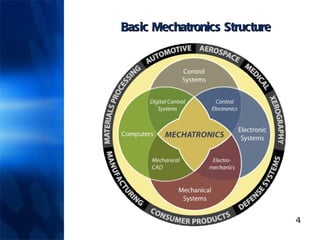
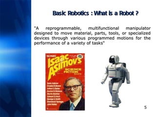
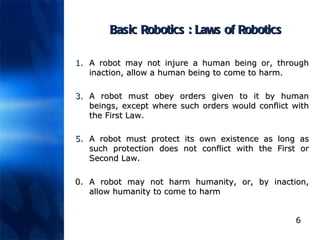
This document provides an introduction to basic robotics, covering fundamental concepts such as the definition of robots, laws of robotics, and key terminology. It also discusses basic electronics necessary for robotics, including components like resistors, capacitors, and transistors, as well as various input and output devices, including sensors and actuators. Additionally, the document outlines different drive mechanisms for mobile robots, highlighting various locomotion systems and their characteristics.