Downloaded 822 times

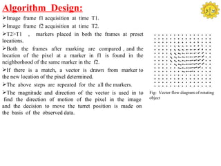
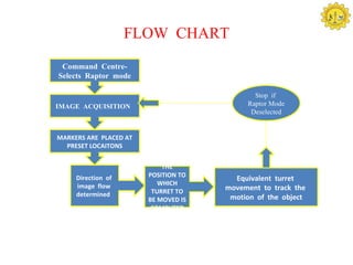
![Algorithm Design:
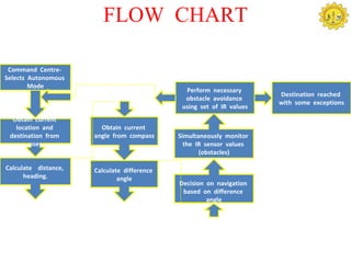
Obtain the Current GPS co-ordinates and the heading reading
from the Compass.
Obtain the Destination Co-ordinates from the user.
Calculate the angle by which the UGV orients with the
desired direction.
Calculated angle provides the rover movement control signals.
The UGV navigates itself to the desired location based on the
IR sensors values which are obtained with respect to the
obstacles.
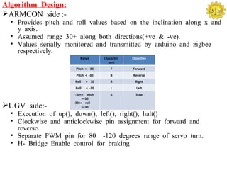
IR(L) IR(M IR(R) Operations
IR(L) IR(M IR(R) Operations ) performed
) performed 1 0 0 Right() and
0 0 0 (No obstacles) Up()
0 0 1 Left() and Up() 1 0 1 Up()
0 1 0 Random[Right() 1 1 0 Right() and
or Left()] and Up()
Up() 1 1 1 Random[Right()
0 1 1 Left() and Up() or Left()] and
down()](https://image.slidesharecdn.com/unmannedgroundvehiclefinal-120613140228-phpapp01/85/Unmanned-Ground-Vehicle-13-320.jpg)
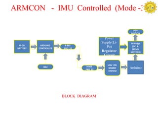
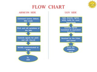
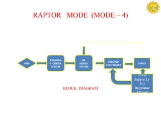


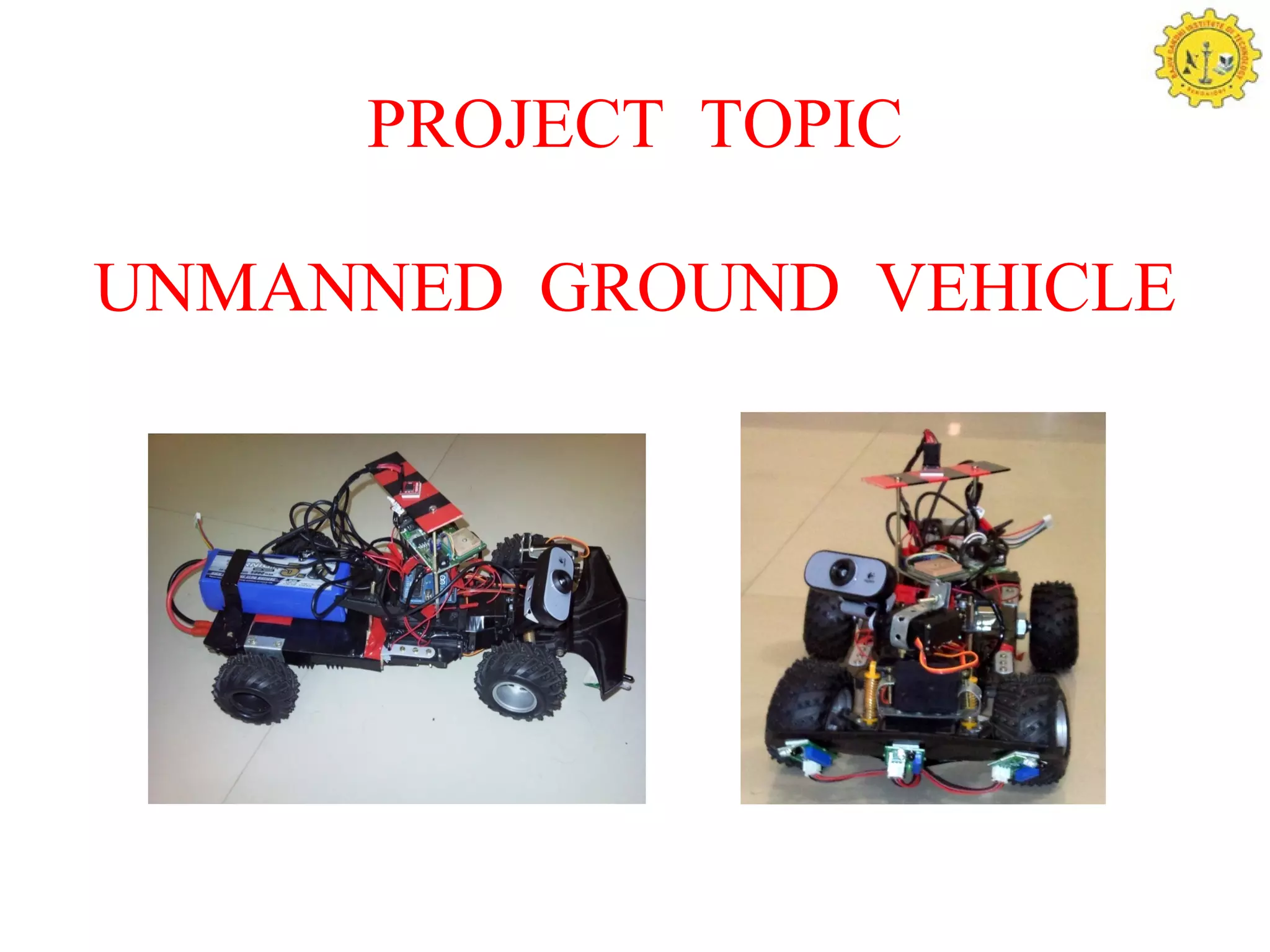
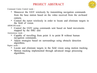
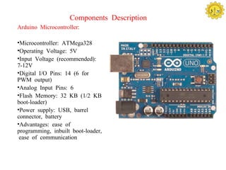
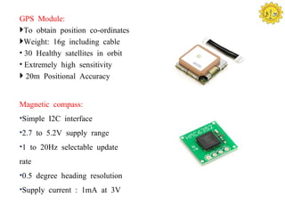
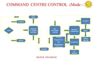
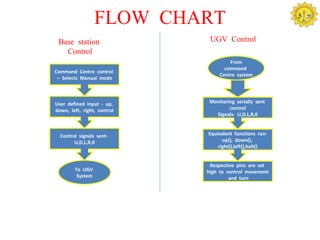
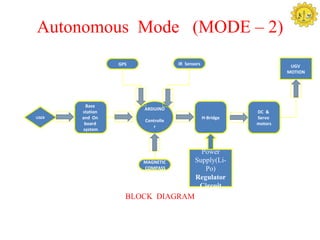
The document discusses unmanned ground vehicles (UGVs) used for military and civilian purposes, detailing their classifications, control modes, and essential components like Arduino microcontrollers and GPS modules. It describes multiple operational modes, including teleoperated, autonomous, and various gesture-controlled functionalities, highlighting technological integrations and applications such as reconnaissance and bomb disposal. Future enhancements include the use of additional sensors and improved motion tracking algorithms to increase UGV capabilities.