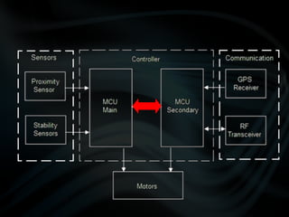
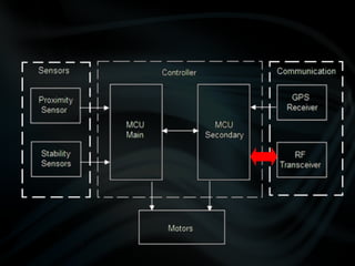
This document describes the design and development of quadrotor unmanned aerial vehicles (UAVs). It discusses the advantages of quadrotors over fixed-wing and helicopter drones. It outlines the design improvements across multiple prototypes to reduce weight and increase lift. It also covers the controller design including sensors, microcontrollers and circuit boards. The document provides details on programming sensors and motors as well as testing procedures.


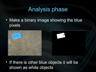
![• Pixel connectivity
• The use of the labeling function
– [label,num]=bwlabel(y,4);
– stats=regionprops(label,'Area','BoundingBox','
PixelList');
• What are the importance of those
functions](https://image.slidesharecdn.com/megafileuploaduavpresentation-121202145618-phpapp01/85/UAV-Presentation-103-320.jpg)