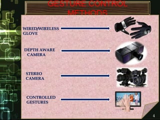
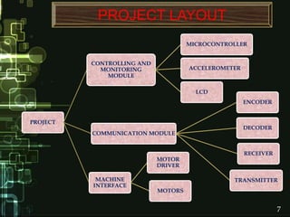
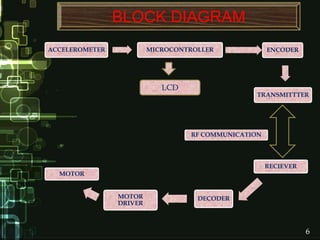
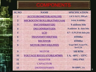
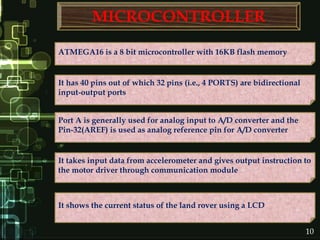
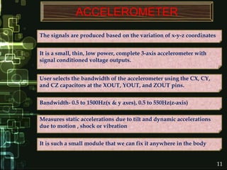
HANDGesture ControlledWIRELESS LAND
ROVER
SAMPAD KUMAR PANDA
SANGRAM KESHARI BHUYAN
SARAT CHANDRA MEHER
SIDDHARTHA KUMAR MUDULI
SUBMITTED BY
GUIDED BY:
PROF. M. MADHURI
DEPT. OF EEE
AIM OF THE PROJECT
REFERENCES
TITLE SLIDE NO.
LITERATURE SURVEY
INTRODUCTION
BLOCK DIAGRAM
CIRCUITS
PROJECT LAYOUT
COMPONENTS
PROGRAMMING
ADVANTAGES
CONCLUSION
FUTURE UPGRADATIONS
CONTENT
06
05
02
01
07
08
12
24
28
25
26
27
1
Where human intervention is not possible or
is not desirable, as in the case of spying, so at
those places we can use service bots and
control the movement
AIM OF THE PROJECT
85% of people with disability are found in
developing countries and about 4% of Indian
population are affected, here service bots
become handy
We can use it in Warfield for bomb detection,
enemy search, etc.
The main challenge in HMI sector (Human Machine Interface) is
making an efficient service bot
These bots interact with the people, so finding natural and easy-to-
use interface is of fundamental importance.
Interaction can be performed using:-
1. Mechanical Devices
2. Gestures
Mechanical devices include certain losses and we need instructions
to use them.
The present technologies make use of geared motors, joysticks,
remotes and sometime hands to move in various directions.
2
INTRODUCTION
WHY GESTURE CONTROL ?
No physical contact with computer
Pick up and manipulate virtual objects
Navigate in a virtual environment
Mouse and Keyboard can be replaced
Interact with the 3D world
It includes our natural responses so can be easily leaned
Interact naturally without any mechanical devices
Communicate at a distance
It is much more efficient and safe to handle
3
GESTURE CONTROL
METHODS
WIRED/WIRELESS
GLOVE
DEPTH AWARE
CAMERA
STEREO
CAMERA
CONTROLLED
GESTURES
4
4
LITERATURE SURVEY
In the journal entitled “MEMS Accelerometer Based Non-specific
User Hand Gesture Recognition” MEMS accelerometer is used to
detect the gestures and compare with the given gesture sequence
This uses a segmentation algorithm to determine the extreme
points of input gesture and converted it into corresponding gesture
codes
Finally the code is matched with the standard pattern and specified
gesture function is performed
Instead of using patterns we use certain hand movements and
simple programming logic to implement the same
PROJECT LAYOUT
PROJECT
CONTROLLING AND
MONITORING
MODULE
MICROCONTROLLER
ACCELEROMETER
LCD
COMMUNICATION MODULE
ENCODER
DECODER
TRANSMITTER
RECEIVER
MACHINE
INTERFACE
MOTOR
DRIVER
MOTORS
7
BLOCK DIAGRAM
ACCELEROMETER MICROCONTROLLER ENCODER
TRANSMITTTER
MOTOR
MOTOR
DRIVER
DECODER
RECIEVER
RF COMMUNICATION
6
LCD
COMPONENTS
SL NO NAME SPECIFICATION
1 ACCELEROMETER(ADXL335) 1.8 V-3.6 V, 350 μA
2 MICROCONTROLLER(ATMEGA16) 8-bit, 0-16Mhz
3 ENCODER(HT12E) 8 address bits
4 DECODER(HT12D) 8 address & data bits
5 LCD 4.7 – 5.3V,8 bit data pin
6 TRANSMITTER(TX02) 433Mhz
7 RECEIVER 433Mhz
8 MOTOR DRIVER(L293D) Vsm=36V,Vem=7V,
Io=1.2A
9 MOTOR 100 RPM
10 VOLTAGE REGULATOR(LM7805) 1 A, -40C – 125C
11 RESISTER 1M, 47K
12 CAPACITOR
13 DIODES(IN4007) 50-1000V, 1A
8
CONTROLLING AND
MONITORING MODULE
9
MICROCONTROLLER
It takes input data from accelerometer and gives output instruction to
the motor driver through communication module
Port A is generally used for analog input to A/D converter and the
Pin-32(AREF) is used as analog reference pin for A/D converter
It has 40 pins out of which 32 pins (i.e., 4 PORTS) are bidirectional
input-output ports
ATMEGA16 is a 8 bit microcontroller with 16KB flash memory
It shows the current status of the land rover using a LCD
10
ACCELEROMETER
The signals are produced based on the variation of x-y-z coordinates
It is such a small module that we can fix it anywhere in the body
It is a small, thin, low power, complete 3-axis accelerometer with
signal conditioned voltage outputs.
User selects the bandwidth of the accelerometer using the CX, CY,
and CZ capacitors at the XOUT, YOUT, and ZOUT pins.
Measures static accelerations due to tilt and dynamic accelerations
due to motion , shock or vibration
Bandwidth- 0.5 to 1500Hz(x & y axes), 0.5 to 550Hz(z-axis)
11
CIRCUITS
INPUTS TO MICROCONTROLLER
12
COMMUNICATION
MODULE
13
LCD
It has separate Vcc and GND pins for display and background
The LCD receives input data from the microcontroller
It has 8 data pins and 3 command pins
It is a 16 X 2 segment display, with 16 pins
14
ENCODER
An encoder is a device that converts information from one format to
another i.e., parallel data into serial data
The HT12E is a 4bit encoder
It is mainly used in interfacing RF and infrared circuits
It receives input from the microcontroller and converts the parallel
data into serial data and then give it to transmitter for transmission.
1 M resistor is connected in between the pins 15 and 16 for
maintaining 434Mhz frequency
15
TRANSMITTER
In this RF system, the digital data is represented as variations in the
amplitude of carrier wave
The corresponding frequency range varies between 30 KHz
& 300GHz
The radio frequency has ability to pass through the obstacles plus it
provides good coverage of 10 meters
TX02 is an RF transmitter where RF stands for “Radio Frequency”
This kind of modulation is known as Amplitude Shift Keying (ASK)
16
CIRCUITS
OUTPUTS FROM MICROCONTROLLER
17
MACHINE INTERFACE
18
RECIEVER
Here the signal contains the serial data
It has 8 number of pins out of which 2 pins are data pins
The RF signal is tuned by a receiver
It receives the RF signal and send it to the decoder
19
DECODER
A decoder is a device which does the reverse operation of an encoder
Original information can be retrieved from the received signal
HT12D converts that serial data into parallel i.e., original data is
recovered
The decoder output is connected to the input of motor driver
47 K resistor is connected in between the pins 15 and 16 for
maintaining 434Mhz frequency
It has number of 18 pins
20
MOTOR DRIVER
The Drive used is L293D, which is also known as H-Bridge
The enable pins are connected to Pin 1 and Pin 9.
The input is 5V and the output is 12V
It has 4 input & 4 output ports, 4 ground and 2 enable pins
It act as an interface between 5V decoder and 12V DC motor
21
MOTOR
Two DC motors with a maximum speed of 100 rpm is used
The chosen rating of motor depends on the size of wheels and their
application
The motors are able to run in both the direction
They operate at an operating voltage of 12V
22
CIRCUITS
MACHINE INTERFACE
23
24
PROGRAMMING
The codes are written using a Atmel AVR tool that is AVR studio 4.
After writing the codes it is stored as a HEX file.
The HEX file is executed using SINAPROG HEX downloader
The details of the code are given in the AVR Studio 4
The file is flashed onto the microcontroller using AVR trainer board
and AVR USB programmer
ADVANTAGES
It proves to be handy for physically challenged people and for
spying
Major advantage is that it’s direction and motion can be controlled
just by hand movement
It can be used in those areas where humans cannot go
It is very much compact and easy to use
25
DRAWBACKS
The motion of the machine interface solely depends on the program.
Incase of any error in the program the interface have to face the
adverse affects
The main drawback is that the land rover can be controlled only in
4-directions. So a better sensing device is required.
Remote power supply is required at the interface, failing which the
land rover may be stuck in critical situations
As no feedbacks are present to verify whether land rover is moving
in correct direction or not is very much difficult
25
FUTURE UPGRADATIONS
On-board control through Keypad/Touch screen
Manual lock and/or auto lock facility
Allowing multiple users to control the land rover
Auto status save on power failure & power on status restore
Using image processing techniques to make it more sensitive
Using gyro sensor to make it more sensitive
26
CONCLUSION
The use of accelerometer makes this project compact and enables
it to move effectively in 4 directions
Cheap components makes it more accessible for the users
Though it consists of less components circuitry is easier and thus
troubleshooting becomes easier
It definitely have a commendable contribution towards the
Service Bots type Machine Interface
27
REFERENCES
http://www.scribd.com/doc/98400320/InTech-Real-Time-Robotic-
Hand-Control-Using-Hand-Gestures
http://www.dimensionengineering.com/info/accelerometers
http://www.atmel.com/devices/atmega16.aspx
Ruize Xu, Shengli Zhou, and Wen J. Li “MEMS Accelerometer Based
Non-specific User Hand Gesture Recognition” IEEE SENSORS
JOURNAL, VOL. 12, NO. 5, MAY 2012
EMBEDDED ROBOTIC “Mobile Robot Design and Applications with
Embedded Systems” By Thomas Bräunl
28
Umesh Yadav, Ankur Tripathi, Sonali Dubey, S.K.Dubey “GESTURE
CONTROL ROBOT”,IJATES, Volume No.02, Issue No. 05, May 2014
Hand Gesture Controlled Wireless Robot

Hand Gesture Controlled Wireless Robot

  • 1.
    HANDGesture ControlledWIRELESS LAND ROVER SAMPADKUMAR PANDA SANGRAM KESHARI BHUYAN SARAT CHANDRA MEHER SIDDHARTHA KUMAR MUDULI SUBMITTED BY GUIDED BY: PROF. M. MADHURI DEPT. OF EEE
  • 2.
    AIM OF THEPROJECT REFERENCES TITLE SLIDE NO. LITERATURE SURVEY INTRODUCTION BLOCK DIAGRAM CIRCUITS PROJECT LAYOUT COMPONENTS PROGRAMMING ADVANTAGES CONCLUSION FUTURE UPGRADATIONS CONTENT 06 05 02 01 07 08 12 24 28 25 26 27
  • 3.
    1 Where human interventionis not possible or is not desirable, as in the case of spying, so at those places we can use service bots and control the movement AIM OF THE PROJECT 85% of people with disability are found in developing countries and about 4% of Indian population are affected, here service bots become handy We can use it in Warfield for bomb detection, enemy search, etc.
  • 4.
    The main challengein HMI sector (Human Machine Interface) is making an efficient service bot These bots interact with the people, so finding natural and easy-to- use interface is of fundamental importance. Interaction can be performed using:- 1. Mechanical Devices 2. Gestures Mechanical devices include certain losses and we need instructions to use them. The present technologies make use of geared motors, joysticks, remotes and sometime hands to move in various directions. 2 INTRODUCTION
  • 5.
    WHY GESTURE CONTROL? No physical contact with computer Pick up and manipulate virtual objects Navigate in a virtual environment Mouse and Keyboard can be replaced Interact with the 3D world It includes our natural responses so can be easily leaned Interact naturally without any mechanical devices Communicate at a distance It is much more efficient and safe to handle 3
  • 6.
  • 7.
    4 LITERATURE SURVEY In thejournal entitled “MEMS Accelerometer Based Non-specific User Hand Gesture Recognition” MEMS accelerometer is used to detect the gestures and compare with the given gesture sequence This uses a segmentation algorithm to determine the extreme points of input gesture and converted it into corresponding gesture codes Finally the code is matched with the standard pattern and specified gesture function is performed Instead of using patterns we use certain hand movements and simple programming logic to implement the same
  • 8.
    PROJECT LAYOUT PROJECT CONTROLLING AND MONITORING MODULE MICROCONTROLLER ACCELEROMETER LCD COMMUNICATIONMODULE ENCODER DECODER TRANSMITTER RECEIVER MACHINE INTERFACE MOTOR DRIVER MOTORS 7
  • 9.
    BLOCK DIAGRAM ACCELEROMETER MICROCONTROLLERENCODER TRANSMITTTER MOTOR MOTOR DRIVER DECODER RECIEVER RF COMMUNICATION 6 LCD
  • 10.
    COMPONENTS SL NO NAMESPECIFICATION 1 ACCELEROMETER(ADXL335) 1.8 V-3.6 V, 350 μA 2 MICROCONTROLLER(ATMEGA16) 8-bit, 0-16Mhz 3 ENCODER(HT12E) 8 address bits 4 DECODER(HT12D) 8 address & data bits 5 LCD 4.7 – 5.3V,8 bit data pin 6 TRANSMITTER(TX02) 433Mhz 7 RECEIVER 433Mhz 8 MOTOR DRIVER(L293D) Vsm=36V,Vem=7V, Io=1.2A 9 MOTOR 100 RPM 10 VOLTAGE REGULATOR(LM7805) 1 A, -40C – 125C 11 RESISTER 1M, 47K 12 CAPACITOR 13 DIODES(IN4007) 50-1000V, 1A 8
  • 11.
  • 12.
    MICROCONTROLLER It takes inputdata from accelerometer and gives output instruction to the motor driver through communication module Port A is generally used for analog input to A/D converter and the Pin-32(AREF) is used as analog reference pin for A/D converter It has 40 pins out of which 32 pins (i.e., 4 PORTS) are bidirectional input-output ports ATMEGA16 is a 8 bit microcontroller with 16KB flash memory It shows the current status of the land rover using a LCD 10
  • 13.
    ACCELEROMETER The signals areproduced based on the variation of x-y-z coordinates It is such a small module that we can fix it anywhere in the body It is a small, thin, low power, complete 3-axis accelerometer with signal conditioned voltage outputs. User selects the bandwidth of the accelerometer using the CX, CY, and CZ capacitors at the XOUT, YOUT, and ZOUT pins. Measures static accelerations due to tilt and dynamic accelerations due to motion , shock or vibration Bandwidth- 0.5 to 1500Hz(x & y axes), 0.5 to 550Hz(z-axis) 11
  • 14.
  • 15.
  • 16.
    LCD It has separateVcc and GND pins for display and background The LCD receives input data from the microcontroller It has 8 data pins and 3 command pins It is a 16 X 2 segment display, with 16 pins 14
  • 17.
    ENCODER An encoder isa device that converts information from one format to another i.e., parallel data into serial data The HT12E is a 4bit encoder It is mainly used in interfacing RF and infrared circuits It receives input from the microcontroller and converts the parallel data into serial data and then give it to transmitter for transmission. 1 M resistor is connected in between the pins 15 and 16 for maintaining 434Mhz frequency 15
  • 18.
    TRANSMITTER In this RFsystem, the digital data is represented as variations in the amplitude of carrier wave The corresponding frequency range varies between 30 KHz & 300GHz The radio frequency has ability to pass through the obstacles plus it provides good coverage of 10 meters TX02 is an RF transmitter where RF stands for “Radio Frequency” This kind of modulation is known as Amplitude Shift Keying (ASK) 16
  • 19.
  • 20.
  • 21.
    RECIEVER Here the signalcontains the serial data It has 8 number of pins out of which 2 pins are data pins The RF signal is tuned by a receiver It receives the RF signal and send it to the decoder 19
  • 22.
    DECODER A decoder isa device which does the reverse operation of an encoder Original information can be retrieved from the received signal HT12D converts that serial data into parallel i.e., original data is recovered The decoder output is connected to the input of motor driver 47 K resistor is connected in between the pins 15 and 16 for maintaining 434Mhz frequency It has number of 18 pins 20
  • 23.
    MOTOR DRIVER The Driveused is L293D, which is also known as H-Bridge The enable pins are connected to Pin 1 and Pin 9. The input is 5V and the output is 12V It has 4 input & 4 output ports, 4 ground and 2 enable pins It act as an interface between 5V decoder and 12V DC motor 21
  • 24.
    MOTOR Two DC motorswith a maximum speed of 100 rpm is used The chosen rating of motor depends on the size of wheels and their application The motors are able to run in both the direction They operate at an operating voltage of 12V 22
  • 25.
  • 26.
    24 PROGRAMMING The codes arewritten using a Atmel AVR tool that is AVR studio 4. After writing the codes it is stored as a HEX file. The HEX file is executed using SINAPROG HEX downloader The details of the code are given in the AVR Studio 4 The file is flashed onto the microcontroller using AVR trainer board and AVR USB programmer
  • 27.
    ADVANTAGES It proves tobe handy for physically challenged people and for spying Major advantage is that it’s direction and motion can be controlled just by hand movement It can be used in those areas where humans cannot go It is very much compact and easy to use 25
  • 28.
    DRAWBACKS The motion ofthe machine interface solely depends on the program. Incase of any error in the program the interface have to face the adverse affects The main drawback is that the land rover can be controlled only in 4-directions. So a better sensing device is required. Remote power supply is required at the interface, failing which the land rover may be stuck in critical situations As no feedbacks are present to verify whether land rover is moving in correct direction or not is very much difficult 25
  • 29.
    FUTURE UPGRADATIONS On-board controlthrough Keypad/Touch screen Manual lock and/or auto lock facility Allowing multiple users to control the land rover Auto status save on power failure & power on status restore Using image processing techniques to make it more sensitive Using gyro sensor to make it more sensitive 26
  • 30.
    CONCLUSION The use ofaccelerometer makes this project compact and enables it to move effectively in 4 directions Cheap components makes it more accessible for the users Though it consists of less components circuitry is easier and thus troubleshooting becomes easier It definitely have a commendable contribution towards the Service Bots type Machine Interface 27
  • 31.
    REFERENCES http://www.scribd.com/doc/98400320/InTech-Real-Time-Robotic- Hand-Control-Using-Hand-Gestures http://www.dimensionengineering.com/info/accelerometers http://www.atmel.com/devices/atmega16.aspx Ruize Xu, ShengliZhou, and Wen J. Li “MEMS Accelerometer Based Non-specific User Hand Gesture Recognition” IEEE SENSORS JOURNAL, VOL. 12, NO. 5, MAY 2012 EMBEDDED ROBOTIC “Mobile Robot Design and Applications with Embedded Systems” By Thomas Bräunl 28 Umesh Yadav, Ankur Tripathi, Sonali Dubey, S.K.Dubey “GESTURE CONTROL ROBOT”,IJATES, Volume No.02, Issue No. 05, May 2014