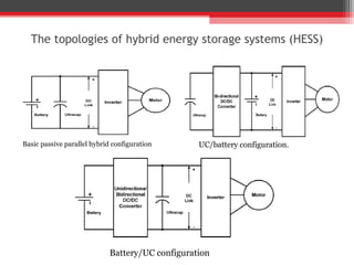
Introduction
• ENERGY storage systems (ESSs) are of critical importance in
  hybrid electric vehicles

• Batteries are one of the most widely used among energy storage
  systems

• In battery-based ESSs, power density of the battery needs to be high
  enough to meet the peak power demand


• Applications of instantaneous power input and output -- batteries
  suffering from frequent charge and discharge operations
• which have an adverse effect on battery life

• To solve the problems hybrid energy storage systems (HESS) have
  been proposed
• The basic idea of an HESS is to combine ultracapacitors (UCs) and
  batteries to achieve a better overall performance

• UCs have a high power density, but a lower energy density. This
  combination inherently offers better performance in comparison to
  the use of either of them alone

• Based on the use of power electronic converters in the configurations
  Several configurations for HESS designs have been proposed.
The topologies of hybrid energy storage systems (HESS)


Basic passive parallel hybrid configuration       UC/battery configuration.


                             Battery/UC configuration
DESIGN CONSIDERATIONS
        of Hybrid energy storage systems
• Voltage Strategy of the Two Energy Sources
       i) VBatt < Vuc = Vdc ii) VBatt = Vuc = Vdc iii) VBatt = Vuc = Vdc

• Effective Utilization of UC Stored Energy


• Protection of the Battery From Overcurrent
• HESS Total Cost
   i) UC cost is a major component of the overall HESS system cost
   ii) Power handling capacity of the converter is another important
  factor
PROPOSED
                Hybrid energy storage systems


• Conventional HESS connects the UC via a dc/dc converter to satisfy the
  real-time peak power demands of the powertrain controller
• This will require the dc/dc converter to have the same power capability as
  the UC bank or at least higher than the maximum possible demand value

• The proposed HESS achieves this in a different way, which can be
  considered an application of the averaging concept
• Different from the conventional HESS designs, the high-voltage dc link is
  allowed to vary in a predefined ratio.
Modes of Operation

Vehicle Low Constant Speed
Operation
         If Pdmd is equal to or
smaller than Pconv , we call this
operating condition the low
constant speed mode


 Vehicle High Constant
 Speed Operation
      In the high constant speed
 operating mode, Pdmd > Pconv ,
 (Condition: VUC < VBatt )
  Therefore, the main power diode
 is forward biased.
Energy flow of the
Acceleration mode phase I
•At the beginning of the
acceleration mode,
   assume VUC >VBatt .
•Since Pconv < Pdmd, VUC will
keep decreasing

•Energies from the UC and the
dc/dc converter are both
supporting the vehicle
acceleration.


Energy flow of the
Acceleration mode phase II
    In the high constant speed
operating mode, if Pdmd <Pconv ,
the power difference between
Pconv and Pdmd will be used to
charge the
UC.
Energy flow of Regenerative
braking phase I when VUC< VUC _tgt
        In phase I, the regenerative
power will be injected into the UC only

   When depending VUC < target UC
          Boost Operation


Energy flow of Regenerative
braking phase I when VUC>=VUC _tgt
  voltage VUC_tgt >= to the target VUC
              No Operation


Energy flow Regenerative braking
phase II
   The dc/dc converter will work in
buck mode to convey the energy from the
UC to the battery
Conclusion
• The new design is able to fully utilize the power capability of
  the UCs without requiring a matching power dc/dc converter.

• Smoother load profile is created for the battery pack – results
  power requirement of the battery pack reduced

• Drivability of the vehicle at low temperatures can be improved
  as well

• proposed HESS requires a smaller size dc/dc converter to
  convey energy to charge the UC bank, while still utilizing up to
  75% of the UC energy

• A relatively constant load profile is created for the battery

• by using the topology which is good for the life of the battery
Thank You

A New Battery/Ultra Capacitor Hybrid Energy Storage System for Electric, Hybrid, and Plug-In Hybrid Electric Vehicles

  • 2.
    Introduction • ENERGY storagesystems (ESSs) are of critical importance in hybrid electric vehicles • Batteries are one of the most widely used among energy storage systems • In battery-based ESSs, power density of the battery needs to be high enough to meet the peak power demand • Applications of instantaneous power input and output -- batteries suffering from frequent charge and discharge operations • which have an adverse effect on battery life • To solve the problems hybrid energy storage systems (HESS) have been proposed
  • 3.
    • The basicidea of an HESS is to combine ultracapacitors (UCs) and batteries to achieve a better overall performance • UCs have a high power density, but a lower energy density. This combination inherently offers better performance in comparison to the use of either of them alone • Based on the use of power electronic converters in the configurations Several configurations for HESS designs have been proposed.
  • 4.
    The topologies ofhybrid energy storage systems (HESS) Basic passive parallel hybrid configuration UC/battery configuration. Battery/UC configuration
  • 5.
    DESIGN CONSIDERATIONS of Hybrid energy storage systems • Voltage Strategy of the Two Energy Sources i) VBatt < Vuc = Vdc ii) VBatt = Vuc = Vdc iii) VBatt = Vuc = Vdc • Effective Utilization of UC Stored Energy • Protection of the Battery From Overcurrent • HESS Total Cost i) UC cost is a major component of the overall HESS system cost ii) Power handling capacity of the converter is another important factor
  • 6.
    PROPOSED Hybrid energy storage systems • Conventional HESS connects the UC via a dc/dc converter to satisfy the real-time peak power demands of the powertrain controller • This will require the dc/dc converter to have the same power capability as the UC bank or at least higher than the maximum possible demand value • The proposed HESS achieves this in a different way, which can be considered an application of the averaging concept • Different from the conventional HESS designs, the high-voltage dc link is allowed to vary in a predefined ratio.
  • 7.
    Modes of Operation VehicleLow Constant Speed Operation If Pdmd is equal to or smaller than Pconv , we call this operating condition the low constant speed mode Vehicle High Constant Speed Operation In the high constant speed operating mode, Pdmd > Pconv , (Condition: VUC < VBatt ) Therefore, the main power diode is forward biased.
  • 8.
    Energy flow ofthe Acceleration mode phase I •At the beginning of the acceleration mode, assume VUC >VBatt . •Since Pconv < Pdmd, VUC will keep decreasing •Energies from the UC and the dc/dc converter are both supporting the vehicle acceleration. Energy flow of the Acceleration mode phase II In the high constant speed operating mode, if Pdmd <Pconv , the power difference between Pconv and Pdmd will be used to charge the UC.
  • 9.
    Energy flow ofRegenerative braking phase I when VUC< VUC _tgt In phase I, the regenerative power will be injected into the UC only When depending VUC < target UC Boost Operation Energy flow of Regenerative braking phase I when VUC>=VUC _tgt voltage VUC_tgt >= to the target VUC No Operation Energy flow Regenerative braking phase II The dc/dc converter will work in buck mode to convey the energy from the UC to the battery
  • 10.
    Conclusion • The newdesign is able to fully utilize the power capability of the UCs without requiring a matching power dc/dc converter. • Smoother load profile is created for the battery pack – results power requirement of the battery pack reduced • Drivability of the vehicle at low temperatures can be improved as well • proposed HESS requires a smaller size dc/dc converter to convey energy to charge the UC bank, while still utilizing up to 75% of the UC energy • A relatively constant load profile is created for the battery • by using the topology which is good for the life of the battery
  • 11.